PID Loop Tuning on PLCs: Siemens S7 & Allen Bradley ControlLogix Practical Guide (Updated July 2026) (Updated July 2026)
In India's process industries — chemical plants around Ratnagiri, pharma bulk-drug manufacturers in Pune's Ambegaon MIDC, and food processing lines in Sangli — a PID (Proportional-Integral-Derivative) loop is the single most critical piece of control software running. AURIC's ₹71,343 crore investment corridor has brought in new process plants where PID performance directly translates to product quality and energy costs: a ±0.5°C temperature control in a pharmaceutical reactor is the difference between batch acceptance and batch rejection. Yet PID tuning remains one of the most poorly taught skills in PLC training — most courses explain what P, I, and D mean, but stop short of showing you how to actually tune a real loop. This guide walks through both manual and auto-tuning methods on the two most common PLC platforms in India's process industry: Siemens S7-1200/S7-1500 using TIA Portal PID, and Allen Bradley ControlLogix using Studio 5000 PIDE instruction.
- PID stands for Proportional-Integral-Derivative — three independent correction terms that together keep a process at its setpoint automatically
- P gain (Kp) eliminates most of the error; I gain (Ti) eliminates steady-state offset; D gain (Td) damps oscillation — tune them in that order
- Siemens TIA Portal uses PID_Compact and PID_3Step function blocks with built-in auto-tune via the commissioning wizard
- Allen Bradley Studio 5000 uses the PIDE instruction with Process Model Tuning and built-in Auto-tune
- Three most common PID problems: oscillation (Kp too high), slow response with overshoot (Ti too long), and integral windup (no output limits set)
What Is a PID Loop and Why Does Tuning Matter?
A PID controller is a feedback algorithm that continuously calculates an error value (the difference between a desired setpoint and a measured process variable) and applies a correction to the process actuator to minimise that error. In a temperature control loop: the setpoint is the target temperature (say, 85°C), the process variable is the actual measured temperature from a thermocouple or PT100 sensor, and the output is the percentage opening of a steam valve or the power percentage to an electric heater. In a pressure loop: setpoint is desired pressure, process variable is the pressure transmitter reading, output is a compressor speed or valve position. Tuning matters because an untuned or badly tuned PID loop causes real, measurable problems: a Kp that is too high causes oscillation (temperature hunting up and down around setpoint, burning product and wasting energy), a Ti that is too short causes overshoot (temperature blows past setpoint before settling), and an unset output limit causes integral windup (the integral term accumulates to maximum while the actuator is already fully open, causing a massive overshoot when it finally gets control). In process industries, poor PID tuning directly causes product quality failures, energy waste, and accelerated equipment wear.
P, I, and D: What Each Term Does and the Order to Tune Them
The three terms of a PID controller each address a different aspect of control. Proportional (P): the output is proportional to the current error — larger error produces a larger correction. Kp (proportional gain) is the multiplier. High Kp = fast response but tends to overshoot and oscillate; low Kp = slow, sluggish response. Integral (I): the output is proportional to the accumulated error over time — it exists specifically to eliminate the steady-state offset that P alone always leaves (the temperature that settles at 83°C instead of 85°C because the P term output is exactly balanced against process load). Ti (integral time) is usually tuned in seconds — lower Ti = stronger integration, faster offset elimination, but also faster oscillation risk. Derivative (D): the output is proportional to the rate of change of error — it damps oscillation by reducing output when the error is decreasing rapidly. Td (derivative time) is often set to zero on noisy processes because D amplifies sensor noise. Tuning sequence: set I and D to minimum (or zero), increase Kp until the loop just starts oscillating, then back off by 30–40%. Add I slowly until offset is eliminated. Add D only if the loop still oscillates after I tuning. This is the Ziegler-Nichols ultimate gain method in its simplified manual form.
PID Tuning on Siemens S7-1200 and S7-1500 Using TIA Portal
Siemens TIA Portal v16+ includes two main PID function blocks: PID_Compact for continuous single-loop control (most temperature, pressure, flow loops) and PID_3Step for valve positioning (where the actuator motor needs separate open and close digital outputs). To add PID_Compact to your project: open a function block in TIA Portal, drag PID_Compact from the Technology Objects folder in the hardware catalogue, connect your process variable (analogue input scaled to engineering units) to the Input pin and your output (0.0–100.0 scaled to the analogue output) to the Output pin. Configure setpoint via the Setpoint input pin or hardcode it. Commissioning wizard: right-click the PID_Compact instance → Commissioning → open the Commissioning panel in online mode. Run 'Pretuning' first — the PLC applies a step change to the output and measures the process response (process gain, dead time, time constant). From the pretuning result, it calculates initial P, I, D values. Then run 'Fine tuning' for optimisation. The auto-tune result fills in the PID parameters automatically. Manual adjustment of the auto-tuned values is almost always needed for aggressive loops (fast flow or fast temperature transitions) — use the manual mode override to test your tuned parameters by stepping the setpoint and watching the response curve on the trend screen.
PID Tuning on Allen Bradley ControlLogix Using Studio 5000 PIDE
Allen Bradley ControlLogix programs PID using the PIDE (Enhanced PID) instruction in Studio 5000. Key parameters: Setpoint (SP), Process Variable (PV), Control Variable output (CV), gains Kp, Ti (minutes), Td (minutes), CVH and CVL (output limits — always set these). Add a PIDE instruction to a ladder rung in a periodic task (50ms to 250ms execution interval is typical for most process loops). Connect PV to your analogue input tag (scaled to engineering units — not raw 0-32767 counts). Connect CV to your analogue output tag. To run auto-tune: in Studio 5000 online, right-click the PIDE instruction → Properties → Process Model tab. Set the Process Type (integrating or self-regulating — most temperature and pressure loops are self-regulating). Set TuneStart = 1 in your program or via Monitor Tags. The PIDE runs a step test, measures the process model, and calculates PID gains. View the calculated gains on the Tuning tab after the test completes. Critically: Allen Bradley's PIDE uses ISA-standard PID (not parallel), and Ti is in minutes not seconds — always check the units when comparing parameters between a Siemens and Allen Bradley installation to avoid a factor-of-60 error in your integral time.
| PID Problem | Symptom | Root Cause | Fix |
|---|---|---|---|
| Oscillation | PV hunts around setpoint | Kp too high | Reduce Kp 25–30% |
| Slow response | PV crawls to setpoint | Kp too low | Increase Kp in 20% steps |
| Steady-state offset | PV stable but below SP | No or weak integral | Reduce Ti until offset gone |
| Integral windup | Massive overshoot after disturbance | No output limits / no AWG | Set CVH/CVL, enable anti-windup |
| D noise chatter | CV output chatters rapidly | Td too high on noisy signal | Set Td to 0 or add derivative filter |
Five Common PID Problems and Exactly How to Fix Them
Five PID problems you will encounter in Indian process plant commissioning. Problem 1 — Oscillation: the process variable continuously hunts above and below setpoint. Fix: reduce Kp by 25–30%; if still oscillating, also increase Ti. Problem 2 — Slow response, no oscillation: the process variable crawls toward setpoint. Fix: increase Kp in 20% steps, watching for oscillation. Problem 3 — Steady-state offset (temperature stabilises 2–3 degrees below setpoint): fix by reducing Ti until offset disappears; pure proportional control always leaves an offset. Problem 4 — Integral windup: after a major disturbance (e.g., a cold product batch loaded into a reactor), the output hits 100% and stays there long after setpoint is reached, causing massive overshoot. Fix: always set CVH (output upper limit) and CVL (lower limit) in the PIDE instruction, and enable the AWG (anti-windup gain) feature on Siemens PID_Compact. Problem 5 — Derivative noise amplification: the CV output chatters rapidly at high frequency. Fix: reduce Td to zero if the loop is stable without it; if D is required, add a derivative filter (DTCoefficient in Siemens PID_Compact, TdFilter in Allen Bradley PIDE). These five fixes solve over 90% of the PID problems you encounter at commissioning.
PID Loop Training in India: Where and How to Learn
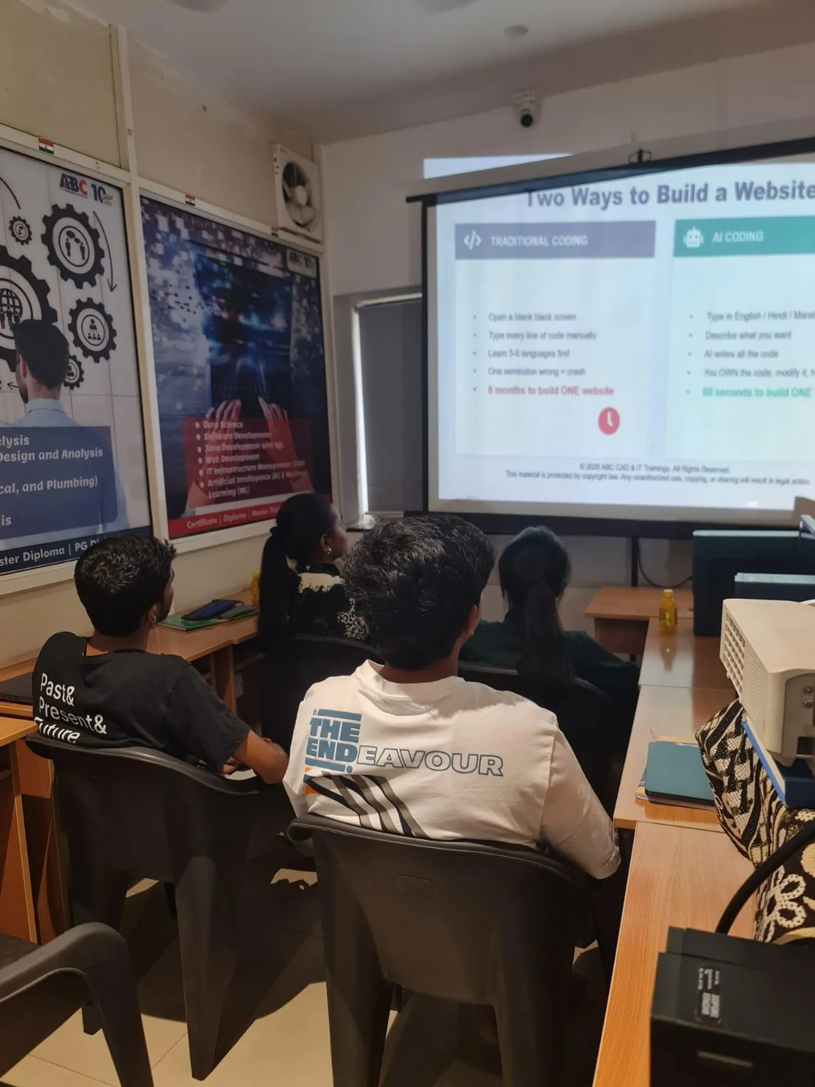
PID loop tuning is a hands-on skill that genuinely requires real process exposure to develop confidence. In India, the fastest learning path is: understand the theory (P, I, D functions, Ziegler-Nichols tuning rules), practise on a simulator (Siemens PID_Compact with PLCSIM Advanced running a simulated process model, or MATLAB Control System Toolbox if available), then commission real loops under supervision. ABC Trainings covers PID fundamentals and hands-on TIA Portal PID_Compact tuning in its 'Industry 4.0 with AI & Industrial Automation' course. Students practise on temperature control rigs with real thermocouples and heaters — not just software simulations. Maharashtra's CMYKPY scheme provides eligible candidates ₹6,000–₹10,000 monthly during the apprenticeship phase of automation training. Process engineers from Siemens India, L&T Electrical & Automation, and Bosch Rexroth India are among the most sought-after professionals in India's process industry — and their edge is consistently being able to commission a PID loop at site rather than having to call the OEM. Call +91 7039169629 or WhatsApp 7774002496 for batch dates.
Maharashtra's CMYKPY (Chief Minister Yuva Karya Prashikshan Yojana) provides eligible engineering candidates a ₹6,000–₹10,000 monthly stipend during the apprenticeship phase of process control and PID training — and PMKVY 4.0 covers PLC and industrial automation under the ESSCI qualification framework.Get the Industrial Automation Brochure + Fees + Batch Dates on WhatsApp
Free 1:1 counselling. Placement track record. CMYKPY/PMKVY eligibility check.
💬 Get Brochure on WhatsApp📞 Call 7039169629About the author: Rutuja Maske, Electrical & Automation Trainer, ABC Trainings.
Visit Our Centers
- Wagholi (Pune): 1st Floor, Laxmi Datta Arcade, Pune-Ahilyanagar Highway. Call 7039169629
- Hadapsar (Pune HQ): 1st Floor, Shree Tower, opp. Vaibhav Theater, Magarpatta. Call 7039169629
- Cidco (Chh. Sambhajinagar): Kalpana Plaza, opp. Eiffel Tower, N-1 Cidco. Call 7039169629
- Osmanpura (Chh. Sambhajinagar): S.S.C Board to Peer Bazar Road, near Jama Masjid. Call 7039169629
- Sangli: Shubham Emphoria, 1st Floor, Above US Polo Assn., Sangli-Miraj Rd, Vishrambag. Weekend batches available. Call 7039169629
FAQs
What does PID stand for in PLC programming?
PID stands for Proportional-Integral-Derivative — three mathematical terms that together form a feedback control algorithm. The proportional term corrects proportional to the current error, the integral term eliminates steady-state offset by integrating error over time, and the derivative term damps oscillation by responding to the rate of change of error.
What is the difference between PID_Compact and PID_3Step in Siemens TIA Portal?
PID_Compact is for continuous output control — it outputs a percentage (0.0–100.0) to an analogue output controlling a valve, heater, or VFD speed. PID_3Step is for positional control of a motorised valve with separate digital outputs for 'open' and 'close' — it drives the valve motor for calculated time intervals to reach the desired position. Choose PID_Compact for most loops; use PID_3Step only when you have a motor-driven valve with no position feedback.
How do I fix integral windup in a PID loop?
Integral windup occurs when the integral term accumulates while the output is saturated (fully open or closed), causing a large overshoot when the process recovers. Fix it by: (1) setting CVH and CVL output limits on the PIDE or PID_Compact instruction so output cannot exceed the physical range, and (2) enabling the anti-windup feature (AWG in Siemens, AWE in Allen Bradley PIDE) which stops integrating when the output limit is reached.
Which PID tuning method is best for beginners?
For beginners, start with manual tuning using the simplified Ziegler-Nichols approach: set I and D to minimum, increase Kp until the loop oscillates steadily, back off by 30%, then add I slowly. Once you understand how each parameter affects the response curve, practise with the auto-tune wizard in TIA Portal (PID_Compact Commissioning) or Studio 5000 (PIDE Process Model). Auto-tune gives a good starting point that you then refine manually.