NX CAM Essentials Beginners Guide Episode 1: Introduction and First Machining Setup (Updated June 2026) (Updated June 2026)
Siemens NX CAM is the industry-leading Computer-Aided Manufacturing software used by Bajaj Auto, Tata Technologies, Mahindra, Force Motors, and virtually every serious Tier-1 automotive component manufacturer in Maharashtra. The AURIC investment cycle in Chhatrapati Sambhajinagar — ₹71,343 crore committed, 62,405 jobs projected — is creating consistent demand for CNC programmers who know NX CAM, not just basic G-code. Episode 1 of this NX CAM Essentials series starts at the very beginning: how to switch into the Manufacturing module inside NX, what the interface shows you, and how to set up your geometry, workpiece, and Machine Coordinate System before you even think about creating a machining operation.
- NX CAM lives inside Siemens NX — switch from Design to Manufacturing using Application > Manufacturing in the menu
- The four geometry views in NX CAM (MCS, Workpiece, Part, Blank) must be set up correctly or your toolpaths will be wrong or fail to generate
- MCS (Machine Coordinate System) defines the origin and orientation of your part relative to the CNC machine spindle — always verify this against your part drawing
- The Workpiece geometry is the bounding stock (raw material); Part geometry is the finished shape; the difference between them is what gets machined away
- Once MCS and geometry are set, you are ready to create operations in Episode 2 — toolpaths, simulation, and post-processing
What is NX CAM and How Does It Fit Into the Manufacturing Workflow?
NX CAM is the CAM (Computer-Aided Manufacturing) module inside Siemens NX — the same software package used for NX CAD 3D modelling. The manufacturing workflow is: design the part in NX CAD, switch to NX Manufacturing, set up your machining environment, create machining operations that define how each feature gets cut, generate the toolpaths, run simulation to verify, then post-process to output G-code for the CNC machine. Companies like Bajaj Auto (Waluj), Endurance Technologies, Tata Technologies (Pune), and Bharat Forge (Pune) all use NX CAM for high-precision automotive and aerospace components. What most people don't realise is that CNC programmers who know NX CAM can command ₹2–4 LPA more than peers who only know MASTERCAM or manual G-code writing.

Opening the Manufacturing Module in Siemens NX
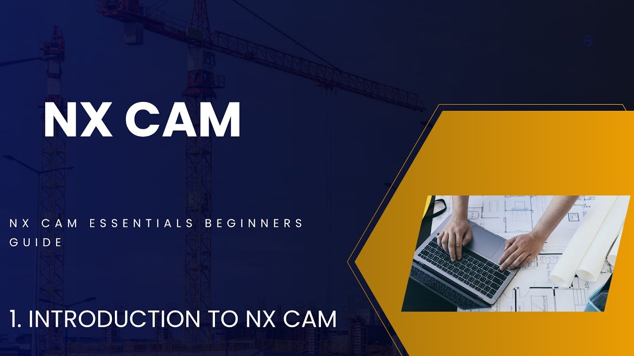
To open NX Manufacturing, you need to have an NX part file open — either a 3D model you designed in NX CAD, or an imported STEP/IGES file from SolidWorks or CATIA. With the part open, go to the Application menu in the top ribbon and select Manufacturing. NX switches your workspace to the Manufacturing environment — a different ribbon with machining-specific menus, and the Operation Navigator appears on the left side. If you see "No Manufacturing Setup Exists," that's expected — you'll create one now. The video above from our ABC Trainings YouTube channel walks through this exact switch from a blank NX session to the Manufacturing module with a sample part.
| NX CAM Setup Element | What It Defines | Common Mistake |
|---|---|---|
| MCS (Machine Coordinate System) | Part origin and axis orientation relative to CNC machine | Wrong origin = all toolpaths offset, parts scrapped |
| Part Geometry | Finished shape to be achieved | Forgetting to select all solid bodies in assembly |
| Workpiece (Blank) | Raw material stock shape and size | Undersized blank = toolpath generates outside stock |
| Tool Library | Cutting tools used for each operation | Wrong diameter entered = incorrect depth/feed calculations |
| Operation Navigator | Sequence of all machining operations | Wrong order (finishing before roughing) = poor surface or tool breakage |
Understanding the NX CAM Interface: Operation Navigator and Geometry Views
The NX CAM interface has three key areas you need to understand. The Operation Navigator (left panel) is your project tree — it shows your machine setup, geometry groups, tool groups, and all your machining operations in sequence. The Graphics Window (centre) shows your 3D part. The Resource Bar (right) gives quick access to tool libraries and templates. Inside the Operation Navigator, you'll see four parent nodes: Machine Tool (controller type), Geometry (MCS and part setup), Methods (machining methods like roughing and finishing), and Tool (cutting tools). Everything you create hangs off one of these four nodes. Get comfortable navigating this tree — every NX CAM operation you create for the rest of your career will appear here.

Setting Up the Machine Coordinate System (MCS)
The Machine Coordinate System (MCS) defines where the origin of your part will be relative to the CNC machine's reference point. It's the most critical setup step in NX CAM — if the MCS is wrong, every toolpath will be offset and your machined part will come out wrong. To set MCS, right-click the MCS node in the Operation Navigator and select Edit. In the dialog, you can set the origin by clicking a point on your part (typically a corner, a hole centre, or the top face centre), and orient the axes to match how the part will sit in the machine vice or fixture. For most milling jobs, Z+ points away from the machine table (up toward the spindle) and X and Y follow the part geometry. Always verify MCS against your process sheet before generating any toolpaths.
Defining Part, Workpiece, and Blank Geometry
After setting MCS, you need to define your geometry — this tells NX CAM what shape is being machined and what the raw material looks like. Part geometry is the finished 3D model — what you want the final part to look like after all machining is done. Workpiece geometry is the raw stock — typically a rectangular billet or a casting that represents the starting material. NX CAM uses the difference between Workpiece and Part to determine where material needs to be removed. In the Operation Navigator, right-click WORKPIECE and select Edit. Specify the Part geometry (select your finished solid body) and the Blank geometry (create an automatic bounding box or select a user-defined stock solid). Once both are set, NX knows exactly what needs to be machined.
Creating Your First Tool and Verifying Setup Before Episode 2
With MCS and geometry defined, the last step of Episode 1 setup is creating your first cutting tool. In the Create Tool dialog (insert > Tool), select your tool type (Mill for milling, Drill for drilling), enter the tool diameter, number of flutes, and cutting length. Give it a meaningful name like EM16-4FL for a 16mm 4-flute end mill. NX adds the tool to your Tool node in the Operation Navigator. At this point, your NX CAM setup is complete and you're ready for Episode 2: creating machining operations, generating toolpaths, running 3D Dynamic Simulation, and post-processing. CNC programmers who can set up an NX CAM job from scratch earn ₹3.5–5.5 LPA fresher at companies like Bajaj Auto, Mahindra, and Tata Technologies in Pune and Sambhajinagar. Call 7039169629 to join the next batch.
Get the AI Powered Product Design, Analysis & Simulation Brochure + Fees + Batch Dates on WhatsApp
Free 1:1 counselling. Placement track record. CMYKPY/PMKVY eligibility check.
💬 Get Brochure on WhatsApp📞 Call 7039169629About the author: Rahul Patil. 12 yrs experience training mechanical and CAD/CAM engineers across Maharashtra.
Visit Our Centers
- Wagholi (Pune): 1st Floor, Laxmi Datta Arcade, Pune-Ahilyanagar Highway. Call 7039169629
- Hadapsar (Pune HQ): 1st Floor, Shree Tower, opp. Vaibhav Theater, Magarpatta. Call 7039169629
- Cidco (Chh. Sambhajinagar): Kalpana Plaza, opp. Eiffel Tower, N-1 Cidco. Call 7039169629
- Osmanpura (Chh. Sambhajinagar): S.S.C Board to Peer Bazar Road, near Jama Masjid. Call 7039169629
- Sangli: Shubham Emphoria, 1st Floor, Above US Polo Assn., Sangli-Miraj Rd, Vishrambag. Weekend batches available. Call 7039169629
FAQs
Do I need to know NX CAD to start learning NX CAM?
Basic NX CAD knowledge is helpful — knowing how to navigate the 3D model, select faces and edges, and understand the solid body structure makes NX CAM setup easier. However, ABC Trainings covers the minimum necessary NX CAD concepts at the start of the NX CAM module, so you don't need prior NX CAD experience to join the course. You do need to understand basic CNC machining concepts: what milling, drilling, and turning operations are.
What is the difference between NX CAM and MASTERCAM?
NX CAM and MASTERCAM are both professional CAM systems, but they serve different market segments. NX CAM is used primarily by large OEMs and Tier-1 suppliers — Bajaj Auto, Tata Technologies, Bharat Forge, GE Aviation, and aerospace manufacturers. It integrates directly with NX CAD for associative machining. MASTERCAM is widely used by job shops and smaller machining operations. In the Pune and Sambhajinagar automotive belt, NX CAM proficiency gives access to higher-salary positions at larger manufacturers.
Which industries in Pune and Sambhajinagar use Siemens NX CAM?
The primary industries using Siemens NX CAM in Pune and Sambhajinagar are: automotive OEMs and Tier-1 suppliers (Bajaj Auto Waluj, Tata Technologies, Mahindra, Endurance), aerospace component manufacturers (Bharat Forge Pune, TASL), and industrial equipment manufacturers. NX CAM is also used in toolroom and jig-and-fixture manufacturing for high-precision work where MASTERCAM or manual programming is insufficient.
How long is the NX CAM course at ABC Trainings and what does it cover?
The NX CAM module at ABC Trainings runs for 60–90 days covering: NX Manufacturing module navigation (Episode 1 — setup), machining operations and toolpath creation (Episode 2), simulation and verification, post-processing for Fanuc and Siemens controllers, and practice on real automotive component files. Available at Wagholi, Hadapsar, Cidco Sambhajinagar, and Osmanpura centers. Call 7039169629 for fees and batch dates.