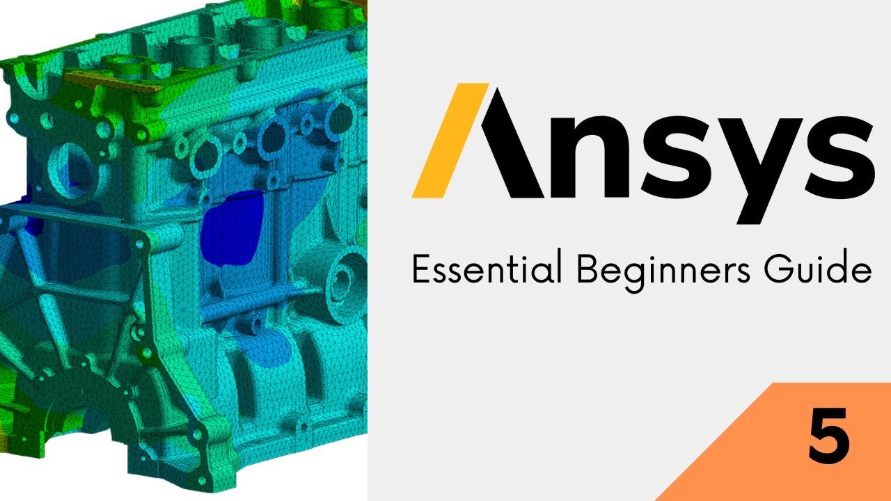
ANSYS Workbench Meshing for Beginners – Types, Quality Metrics & Best Practices (Updated June 2026) (Updated June 2026)
If I had to pick the single skill that separates a beginner ANSYS user from a confident simulation engineer, it would be meshing. A poorly meshed model gives you results that look convincing but are completely wrong — and in automotive or aerospace components, wrong simulation results have real consequences. NASSCOM-Deloitte projects 1.25 million AI-integrated engineering roles by 2027, and FEA-capable mechanical engineers are at the top of the demand list for companies like Bajaj Auto, Tata Tech, and Bosch India. Episode 5 of our ANSYS Workbench Essentials series is dedicated entirely to meshing — because getting this right is the difference between a simulation that you can defend in an engineering review and one that you cannot.
- Meshing divides your 3D geometry into thousands of small elements — the solver calculates stress and deformation at each element's nodes
- Tetrahedra (tet) elements fit complex curved geometries automatically; hexahedra (hex) elements give higher accuracy with fewer elements but require structured geometry
- Skewness below 0.25 is excellent, 0.25 to 0.5 is acceptable, above 0.9 is unacceptable and will cause solver inaccuracy or failure
- Body Sizing sets the global element size; Face Sizing refines specific critical surfaces where stress concentrations are expected
- A mesh independence study runs two or three progressively finer meshes and confirms results converge — a non-negotiable step before trusting your simulation
Why Meshing Is the Foundation of Any FEA Simulation
The mesh is a mathematical discretization of your continuous geometry into discrete elements. The finite element method (FEM) solves the governing equations of stress and deformation at the nodes (corners) of each element. The more elements you use, the closer the solution matches the true mathematical answer — but the longer the solve takes and the more computer memory it needs. Good meshing is about using the right number and type of elements in the right places: fine mesh where stress changes rapidly (notches, holes, fillets), coarse mesh where it changes slowly (large flat surfaces). Engineers at Mahindra Engineering Services and L&T Technology Services spend significant time on meshing strategy precisely because it drives both result accuracy and simulation cost.
Mesh Element Types in ANSYS: Tetrahedra, Hexahedra, and Pyramids
ANSYS Workbench uses two primary 3D element types. Tetrahedral (tet) elements have four nodes at the corners and can fill any arbitrarily shaped volume — this is what ANSYS uses when you click Automatic mesh on complex imported CAD geometry. They are easy to generate but require more elements than hex meshes for the same accuracy. Hexahedral (hex) elements are brick-shaped with eight nodes; they give higher accuracy per element but require sweep-meshable geometry (prismatic shapes, extrusions). ANSYS Workbench also uses pyramid and wedge elements as transition elements where tet and hex regions meet. For most industrial components, a well-controlled tet mesh with second-order elements delivers results within 2 to 5% of the exact solution.
| Mesh Quality Metric | Ideal Value | Acceptable Range | Reject if Above |
|---|---|---|---|
| Skewness | 0 (perfect) | 0 to 0.5 | 0.9 |
| Aspect Ratio | 1 (equilateral) | 1 to 5 | 20 |
| Jacobian Ratio | 1 | 1 to 10 | 30 |
| Orthogonal Quality | 1 (perfect) | 0.5 to 1.0 | 0.1 |
| Element Quality | 1 (perfect cube/tet) | 0.7 to 1.0 | 0.1 |
Automatic vs Manual Meshing: When to Let ANSYS Decide
When you click Generate Mesh in ANSYS Mechanical without any sizing controls, ANSYS uses its Patch-Conforming algorithm to automatically create a tet mesh based on the geometry's curvature and proximity. This is perfectly fine for preliminary analysis and works well for 80% of models. Manual meshing gives you control over element sizes at specific faces, edges, or bodies — essential when your geometry has thin walls, sharp fillets, or stress concentration features. The key insight: always start with the automatic mesh, check mesh quality statistics, and then add manual sizing controls only where quality falls below acceptable thresholds. Don't spend hours on meshing before you know if the model even solves.
Mesh Quality Metrics: Skewness, Aspect Ratio, and Jacobian Explained
ANSYS Mechanical displays mesh quality metrics in the Mesh Details panel under Statistics. Skewness measures how far each element deviates from the ideal shape — 0 is perfect, 1 is completely degenerate. The ANSYS guideline is skewness below 0.9 for structural analysis and below 0.5 for CFD; below 0.25 is excellent. Aspect Ratio measures elongation: elements stretched in one direction perform poorly. Jacobian Ratio checks the geometric mapping quality — values above 20 indicate badly shaped elements near curves. If your average skewness exceeds 0.5, refine the mesh in the problematic region before trusting results from that area.
Mesh Refinement Techniques: Body Sizing, Face Sizing, and Inflation
ANSYS Workbench offers several refinement tools inside the Mesh branch. Body Sizing sets a target element size for an entire body — use this to globally refine without targeting specific features. Face Sizing applies a specific element size to selected faces, ideal for stress concentration zones like bolt holes and fillet radii. Inflation layers add thin prism elements perpendicular to surfaces, capturing boundary layer effects in CFD or accurately resolving bending stress in thin-walled structures. Sphere of Influence lets you refine a spherical region in space, useful when you know stress is concentrated around a specific point but your geometry makes face selection difficult.
Mesh Independence Study: The Step That Makes Your Results Trustworthy
A mesh independence study is the process of solving the same model with progressively finer meshes and comparing a key result — typically the peak Von Mises stress — until the values stop changing significantly. A standard approach: run with the automatic coarse mesh, record peak stress; halve the element size, re-solve, record stress; reduce again. When the result changes by less than 5% between two consecutive mesh refinements, your mesh is considered independent and your results are trustworthy. I've seen students present projects at campus interviews without this step and get grilled immediately. Bajaj Auto and Tata Tech simulation teams run mesh convergence as a mandatory checklist item before any simulation result is used in design decisions.
Maharashtra's Chief Minister Yuva Karya Prashikshan Yojana (CMYKPY) provides engineering graduates with Rs. 6,000-10,000/month stipends for on-the-job training at manufacturing companies. ABC Trainings prepares students for CMYKPY-eligible simulation roles at ANSYS-using firms in Pune's Pimpri-Chinchwad MIDC, Sambhajinagar's AURIC zone, and Kolhapur's Kagal belt.Get the CAD/CAM Brochure + Fees + Batch Dates on WhatsApp
Free 1:1 counselling. Placement track record. CMYKPY/PMKVY eligibility check.
💬 Get Brochure on WhatsApp📞 Call 7039169629About the author: Rahul Patil. 12 yrs experience training mechanical and CAD/CAM engineers across Maharashtra.
Visit Our Centers
- Wagholi (Pune): 1st Floor, Laxmi Datta Arcade, Pune-Ahilyanagar Highway. Call 7039169629
- Hadapsar (Pune HQ): 1st Floor, Shree Tower, opp. Vaibhav Theater, Magarpatta. Call 7039169629
- Cidco (Chh. Sambhajinagar): Kalpana Plaza, opp. Eiffel Tower, N-1 Cidco. Call 7039169629
- Osmanpura (Chh. Sambhajinagar): S.S.C Board to Peer Bazar Road, near Jama Masjid. Call 7039169629
- Sangli: Shubham Emphoria, 1st Floor, Above US Polo Assn., Sangli-Miraj Rd, Vishrambag. Weekend batches available. Call 7039169629
FAQs
How many elements should I use in my ANSYS Workbench mesh?
There is no universal right number — it depends on your geometry, the accuracy needed, and available computing resources. For a simple bracket, 30,000 to 100,000 elements typically gives good results. For a complex automotive component with multiple contacts, 500,000 or more elements may be needed. The practical approach: run an automatic mesh, check quality statistics, add sizing controls where needed, and always confirm with a mesh independence study before trusting the peak stress value.
What is the difference between first-order and second-order elements in ANSYS?
First-order (linear) elements have nodes only at corners and use linear interpolation between them. Second-order (quadratic) elements add midside nodes and use quadratic interpolation, capturing curved geometry and stress gradients far more accurately. In ANSYS Workbench, right-click the Mesh branch, go to Details, and set Element Order to Program Controlled (usually second-order for structural analysis) or Quadratic explicitly. Second-order meshes take longer to solve but give significantly better accuracy in areas with stress concentrations, curved surfaces, and bending-dominated problems.
How do I check mesh quality in ANSYS Workbench?
In ANSYS Mechanical, click the Mesh branch in the tree and look at the Details panel on the left — it shows Statistics including Element Count, Node Count, and a quality metric summary. For a visual quality map, right-click Mesh, select Mesh Metrics, and choose Skewness or Element Quality from the dropdown. ANSYS generates a colour-coded contour map over the mesh and a histogram showing the distribution. Aim for the histogram peak to be in the green (excellent) to yellow (acceptable) region, with minimal elements in the red (poor) region.
What causes the mesh to fail in ANSYS and how do I fix it?
Mesh generation fails most commonly for three reasons. First, geometry with very thin gaps or slivers that ANSYS cannot fill — fix by simplifying geometry in DesignModeler. Second, geometry with zero-thickness surfaces — ensure all bodies are solid before meshing. Third, importing damaged CAD with missing faces — use the Geometry check tools in SpaceClaim to heal the model before meshing. For each failure, ANSYS shows a red error message in the Meshing branch; read it carefully as it specifies which face or edge is the problem.