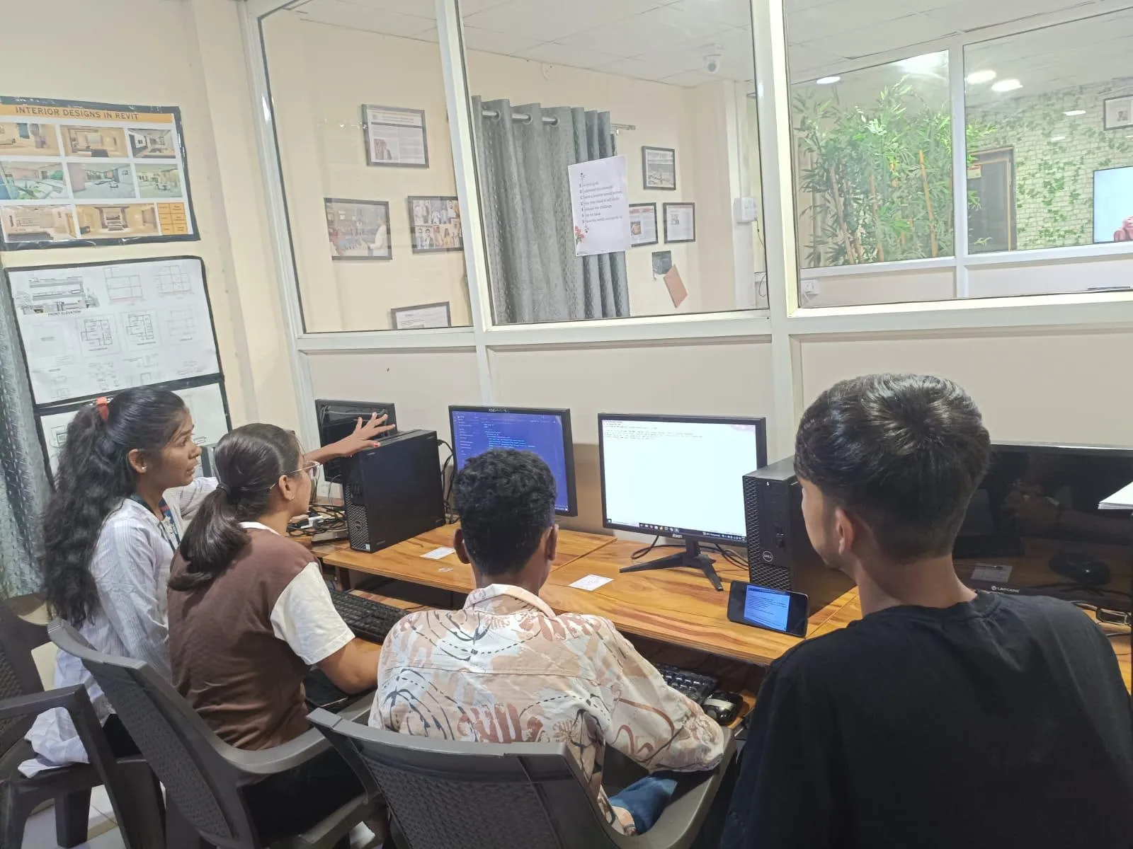
NX CAD Essentials Episode 5: Datum Planes, Reference Geometry, and Solid Primitives for Beginners (Updated June 2026)
Maharashtra's AURIC industrial corridor near Sambhajinagar has attracted Rs 71,343 crore in committed investment and 62,405 manufacturing jobs — at every company in that corridor, NX CAD is the design tool engineers open on day one. In Episode 5 of our NX CAD Essentials series, we cover the reference geometry layer that sits beneath all 3D modeling: datum planes, datum axis, datum CSYS, and solid primitive features. Most NX CAD beginners rush past this foundation to get to sketching and extrude commands — and then wonder why their assemblies don't mate correctly or why their models break when they edit a dimension. Episode 5 prevents those problems before they start.

- Episode 5 covers datum CSYS, datum planes, datum axis, and solid primitive features — the reference geometry foundation for all NX CAD modeling
- Datum planes are the sketch planes for Episode 6's Extrude, Revolve, and Sweep commands — getting them right here prevents assembly errors later
- AURIC corridor: Rs 71,343 crore committed, 62,405 jobs — NX CAD is the design standard at every major AURIC manufacturer
- Solid primitives (Block, Cylinder, Cone, Sphere) are the fastest way to build starting geometry before sketch-based modification
- Fresher NX CAD engineers earn Rs 2.8L-Rs 4.2L in Pune; senior roles at KPIT and Tata Tech reach Rs 10L+
- CMYKPY provides Rs 6,000-Rs 10,000 for NX CAD training at ABC Trainings
What Episode 5 Covers: Reference Geometry Before 3D Modeling
In NX CAD, every 3D model sits inside a reference geometry framework that you define before you create a single sketch. Episode 5 of the NX CAD Essentials series builds this framework: the Datum CSYS (the origin and coordinate system of your part), datum planes (the flat reference surfaces you sketch on), datum axis (the rotational references used for Revolve features and radial patterns), and datum points (precise reference locations for assembly constraints). Many NX beginners skip this and start sketching immediately on the default XY plane — which works for simple parts but breaks down immediately for anything with angled features, cylindrical housings, or assembly mating requirements. Understanding Episode 5 is what prevents the most common NX modeling errors that show up only after an assembly is built.

Datum CSYS: The Origin and Coordinate System Every NX Part Starts With
Every NX CAD part file opens with a default Datum CSYS at the absolute origin (0,0,0). The Datum CSYS defines the X, Y, and Z axes and the three principal planes (XY, XZ, YZ) that NX uses for all geometric calculations. You can define additional datum coordinate systems anywhere in space — offset from the default, at an angle, or aligned to a specific face or edge of an imported part. Understanding the CSYS is critical for: setting up datum planes at the correct orientation for complex feature creation, defining assembly constraints that mate parts at precise positions, and importing STEP or JT files where the origin may not align with your standard design practice. At ABC Trainings, we always start Episode 5 with a deliberate CSYS setup exercise because it establishes the spatial reasoning habit that experienced NX engineers develop over years.
| Reference Feature | What It Does | Common Use Cases | Episode Covered |
|---|---|---|---|
| Datum CSYS | Defines part origin and axes | All parts, imports, assemblies | Episode 5 |
| Datum Plane | Flat sketch reference surface | Inclined faces, offsets, symmetry | Episode 5 |
| Datum Axis | Linear reference for rotation/pattern | Revolve, circular pattern, assembly | Episode 5 |
| Solid Primitive | Block, cylinder, cone, sphere | Starting body for machined parts | Episode 5 |
| Layer Management | Controls visibility by object type | Organise datum vs solid vs sketch | Episode 5 |
Datum Planes: Creating the Reference Planes You Will Sketch On
Datum planes are the flat reference surfaces you draw sketches on before creating parametric features like Extrude or Revolve. NX provides three default datum planes (XZ, XY, YZ) aligned to the CSYS, but you will need custom datum planes for inclined surfaces, mid-planes, offset surfaces, and tangent planes. The most common datum plane types in NX CAD: At Distance (offset parallel to an existing plane by a specified value — used for stepped housings and multi-level features), At Angle (rotated around an axis — used for inclined faces on machined parts), Bisector (midway between two parallel planes — used for symmetry in assemblies), and On Curve (tangent or normal to a curve at a point — used for swept features along complex paths). Every sketch in Episode 6 will be drawn on one of these plane types. Getting comfortable with datum plane creation in Episode 5 means your Episode 6 models will be correctly oriented from the first feature.

Datum Axis and Datum Points: For Rotation, Symmetry, and Assembly Constraints
Datum axis is a linear reference that NX uses for Revolve operations (the axis your sketch profile rotates around), circular pattern positioning (placing 6 holes around a bolt circle requires an axis at the centre), and assembly constraints (aligning a shaft to a bore requires matching their datum axes). Datum axis can be created: coincident with a linear edge, through two datum points, at the intersection of two planes, or along a cylinder's central axis. Datum points are precise reference locations in 3D space — on a curve end, at a face centroid, at a specific XYZ coordinate, or at arc centres. In assembly work, datum points serve as snap references for mating constraints. Both datum axis and datum point features appear in the Part Navigator and can be edited or suppressed like any other feature. They are classified as "reference features" because they have no mass or geometry themselves — they only guide other features.
Solid Primitive Features: Block, Cylinder, Cone, and Sphere in NX CAD
Solid primitives are NX CAD's shortcut commands for creating standard geometric solids without drawing a sketch first. The four main primitives: Block (a rectangular solid defined by length, width, and height — used for housings, bases, and structural members), Cylinder (a circular solid defined by diameter and height — used for shafts, bosses, and spacers), Cone (a tapered solid defined by base diameter, apex diameter, and height — used for tapered pins, funnel shapes, and chamfered entries), and Sphere (a spherical solid defined by diameter — used for ball ends, dome features, and fillets at internal corners). Each primitive is created as a feature in the Part Navigator and can be used as the starting body for subtract and unite Boolean operations. The practical workflow: create a Block primitive for a housing body, then use Hole and Pocket features from Episode 6 to add machined features. This is faster than sketching the full rectangular profile and extruding it when the part has mostly orthogonal geometry.
Layer Management and View Setup in NX CAD: Keeping Your Model Organised
Layer management in NX CAD controls which objects are visible, selectable, and exportable at any given time. NX uses a 256-layer system: by convention, layer 1 is the solid body, layers 11-20 are datum geometry, layers 21-40 are sketch geometry, and layers 61-80 are curves. Assigning datum planes, datum axes, and datum points to dedicated layers means you can hide reference geometry when presenting the model and show it again when editing. The Move to Layer command in the Format menu reassigns features to specific layers. View management controls: Standard views (Top, Front, Right, Isometric) are accessed from the View toolbar; custom named views save a specific orientation for repeated access during section cuts and detail views. At ABC Trainings, we introduce layer discipline in Episode 5 because models built without it — where datum planes and solid bodies share layer 1 — become extremely difficult to select and edit once you have 30+ features.
NX CAD Jobs in Pune and Sambhajinagar: What Episode 5 Skills Enable
After completing Episode 5, you have the reference geometry foundation to start building real 3D parts in Episode 6. This immediately qualifies you to assist on CAD modelling tasks in any manufacturing or design environment — setting up part templates, creating datum frameworks for assemblies, and importing STEP files and establishing correct working planes. In Pune: Bajaj Auto Akurdi, Mercedes-Benz R&D India, KPIT Technologies Hinjewadi, Tata Technologies, and Bosch India Nashik all hire NX CAD operators who understand reference geometry as part of their modelling workflow. In Sambhajinagar: Skoda VW Shendra (Plot A-1/1), Bajaj Auto Waluj (Plot G-137), Endurance Technologies (Plot E-92 MIDC), and Hyosung AURIC plant. Entry salary for Episode 5-6 combined skills: Rs 2L-Rs 3.5L for design trainee roles, growing to Rs 2.8L-Rs 4.2L with Episode 7 assembly and drafting skills added.
CMYKPY Scheme for NX CAD Training in Maharashtra
If you are from Maharashtra and want to learn Siemens NX CAD, the Chhatrapati Mahatma Jyotiba Phule Kaushal Parishay Yojana (CMYKPY) provides Rs 6,000 to Rs 10,000 as a skill incentive for enrolled students at accredited centres. ABC Trainings is MSME-certified and registered under the Government of Maharashtra skill development initiative. Our NX CAD course covers the full Essentials series (Episodes 1-10) plus advanced assembly, NX CAM, and placement preparation with our 200+ hiring partner network. PMKVY 4.0 also covers advanced CAD/CAM skills under the manufacturing sector. Bring your Aadhaar, bank passbook, and latest marksheet on day one. Call 7039169629 or WhatsApp 7774002496 for the next batch at your nearest centre in Pune, Sambhajinagar, or Sangli.
Get the NX CAD Training Brochure + Fees + Batch Dates on WhatsApp
Free 1:1 counselling. Placement track record. CMYKPY/PMKVY eligibility check.
💬 Get Brochure on WhatsApp📞 Call 7039169629About the author: Rahul Patil. 12 yrs experience training engineers across Maharashtra.
Visit Our Centers
- Wagholi (Pune): 1st Floor, Laxmi Datta Arcade, Pune-Ahilyanagar Highway. Call 7039169629
- Hadapsar (Pune HQ): 1st Floor, Shree Tower, opp. Vaibhav Theater, Magarpatta. Call 7039169629
- Cidco (Chh. Sambhajinagar): Kalpana Plaza, opp. Eiffel Tower, N-1 Cidco. Call 7039169629
- Osmanpura (Chh. Sambhajinagar): S.S.C Board to Peer Bazar Road, near Jama Masjid. Call 7039169629
- Sangli: Shubham Emphoria, 1st Floor, Above US Polo Assn., Sangli-Miraj Rd, Vishrambag. Weekend batches available. Call 7039169629
FAQs
What is covered in NX CAD Essentials Episode 5?
Episode 5 covers the reference geometry layer essential to all NX CAD modeling: Datum CSYS (origin and coordinate system), datum planes (sketch reference surfaces), datum axis (rotational references for Revolve and pattern commands), solid primitive features (Block, Cylinder, Cone, Sphere), and layer management for organising model objects. These are the prerequisites for Episode 6's sketch-based parametric modeling.
What are datum planes used for in NX CAD?
Datum planes are flat reference surfaces that you draw 2D sketches on before creating 3D features. Unlike sketching on a default XY or XZ plane, custom datum planes let you sketch on inclined surfaces, offset surfaces, or mid-planes — which is required for almost every real mechanical part beyond simple prismatic shapes. In NX, you can create datum planes at distance, at angle, bisecting two planes, or tangent to curved surfaces.
What is the difference between datum axis and datum CSYS in NX?
Datum CSYS (Coordinate System) is the complete origin framework — X, Y, Z axes and all three principal planes — for positioning and orienting the entire part or assembly. Datum axis is a single linear reference for one specific purpose: defining the rotation axis for a Revolve feature, or the centre axis for a circular pattern command. One CSYS gives you three implicit axes; datum axis creates an additional standalone reference independent of the CSYS.
Do I need to complete Episode 5 before Episode 6 in NX CAD?
Yes. Episode 5 reference geometry knowledge prevents the most common NX modeling errors: sketching on the wrong plane, Revolve features rotating around the wrong axis, and assembly parts that cannot be properly mated because their datum references were not set up correctly. Students who skip Episode 5 and start directly with Episode 6 sketching consistently produce models that break when they try to build assemblies or apply engineering changes.