Verified course outcomes

Creo Parametric281 students trained · 2022–2026 · Maharashtra

Every number on this page is pulled from our admissions backend — paid enrollments, real trainer assignments, branch distribution, currently open job openings, and published 5-star reviews from actual alumni. No marketing fluff.

281

Paid enrollments

Since Jun 2022

5 / 5

Average rating

21 published reviews

19+

Hiring partner roles

Product design + manufacturing

6

Centres offering it

Across Maharashtra

What you'll learn

Master PTC Creo Parametric end to end

For product designers, mechanical & manufacturing engineers

This comprehensive course elevates your knowledge and skills on the process of product development by using PTC Creo Parametric as a virtual CAD tool. Through an engaging project, the instructor guides you through converting a conceptual product into a functional assembly, so you understand how engineering companies tackle the product-development journey end to end.

The course aims to help product designers and engineers develop a product design virtually. Creo is equipped with all the capabilities required to complete a product design — this program covers sketching, modeling, validation of design, and visualizing the product design, so you can apply the same engineering skills confidently on other products and build them out as your portfolio.

Roles this prepares you for

Advanced product designManufacturingVirtual prototyping3D modeling

Course at a glance

Duration

80 hours

Structure

22 sessions

Taught in

English & Hindi

On completion

Course certificate

Course fee

₹18,987

Why this program

What you'll be able to do

The capabilities you build through the Creo Parametric program at ABC Trainings.

Creo’s 2D solutions — Sketch, Layout and Schematics let you quickly sketch ideas, diagram complex systems and create detailed engineering concept drawings

Creo’s 3D solutions — Parametric, Direct and Options Modular let advanced and casual CAD users create 3D models

Assembly — Creo’s assembly environment lets you create and manage large assemblies with ease

Visualization — Creo’s visualization module helps engineers and designers visualize all product data available in any media format

The full syllabus

22-session curriculum, sketches to production drawings

The complete module-by-module syllabus as taught at ABC Trainings. You build from the Creo Parametric basics and sketching through advanced features, sheet-metal design, assemblies and skeletons — finishing with production drawing views, sections and detailing.

01Introduction to the Creo Parametric Basic Modeling Process
  • Creo Parametric Basic Modeling Process
  • Understanding Creo Parametric Concepts
  • Understanding Solid Modeling Concepts
  • Understanding Feature-Based Concepts
  • Understanding Parametric Concepts
  • Understanding Associative Concepts
  • Understanding Model-Centric Concepts
  • Recognizing File Extensions
  • Using the Creo Parametric Interface
  • Understanding the Main Interface
  • Understanding the Folder Browser
  • Understanding the Web Browser
  • Understanding the Ribbon Interface
  • Setting the Working Directory and Opening and Saving Files
  • Managing Files in Creo Parametric
  • Creating Sketcher Geometry
  • Reviewing Sketcher Theory
  • Understanding Design Intent
  • Modifying the Sketcher Display
  • Utilizing Constraints
  • Sketching with on the fly constraints
  • Sketching Lines
  • Sketching Centerlines
  • Sketching Rectangles
  • Sketching Circles
  • Sketching Arcs
  • Sketching Circular Fillets and Chamfers
  • Using Sketcher Tools
  • Understanding Construction Geometry Theory
  • Sketching Points
  • Using Geometry Tools within Sketcher
  • Manipulating Sketches within Sketcher
  • Dimensioning Entities within Sketcher
  • Modifying Dimensions within Sketcher
  • Sketcher Conflicts
  • Placing Sections into Sketcher
  • Creating Sketches for Features
  • Creating Sketches (Sketch Feature)
  • Specifying the Sketch Setup
  • Utilizing Sketch References
  • Using Entity from Edge within Sketcher
02Sketching
  • Advanced Sketching
  • Using Sketched Curves
  • Sketching Ellipses
  • Sketching Elliptical Fillets
  • Sketching Splines
  • Modifying Splines (Basic & Advanced)
  • Importing and Exporting Spline Points
  • Sketching Conics
  • Sketching Text
  • Analyzing Sketcher Convert Options
  • Analyzing Sketcher Dimension Options
  • Sketcher Diagnostic Tools
  • Creating Extrudes, Revolves, and Ribs
  • Creating Solid Extrude Features
  • Adding Taper to Extrude Feature
  • Common Dashboard Options: Extrude Depth
  • Common Dashboard Options: Feature Direction
  • Common Dashboard Options: Thicken Sketch
  • Creating Solid Revolve Features
  • Common Dashboard Options: Revolve Angle
  • Automatically Adding and Removing Material
  • Creating Rib Features
  • Using the Creo Parametric Interface - Part 2
  • Understanding Basic Display Options
  • Analyzing Basic 3-D Orientation
  • Understanding the View Manager
  • Creating and Managing View Orientations
  • Creating Style States using the View Manager
  • Understanding Basic Color and Appearance Options
  • Setting Up New Part Models
03Understanding Creo Parametric Basic Controls
  • Selecting and Editing
  • Understanding Creo Parametric Basic Controls
  • Using Drag Handles and Dimension Draggers
  • Using Keyboard Shortcuts
  • Understanding the Model Tree
  • Selecting Items using Direct Selection
  • Selecting Items using Query Selection
  • Selecting Multiple Components
  • Using the Search Tool
  • Understanding Selection Filters
  • Renaming Objects
  • Editing Features and Regenerating
  • Activating and Editing Models
  • Deleting and Suppressing Items
  • Creating Datum Features: Planes and Axes
  • Creating Datum Features Theory
  • Creating Datum Axes
  • Creating Datum Planes
  • Utilizing Internal Sketches and Embedded Datums
  • Creating Internal Sketches
  • Creating Embedded Datum Features
  • Creating Sweeps and Blends
  • Creating Sweeps with Open Trajectories
  • Creating Sweeps with Closed Trajectories
  • Analyzing Sweep Feature Attributes
  • Creating a Parallel Blend Protrusion or Cut
  • Experimenting with Parallel Blend Attributes
  • Analyzing Parallel Blend Section Tools
04Variable Section & Helical Sweeps
  • Variable Section Sweeps
  • Creating Variable Section Sweeps using a Constant Section
  • Creating Variable Section Sweeps Normal to Trajectory
  • Creating Variable Section Sweeps using Constant Normal Direction
  • Creating Variable Section Sweeps Normal to Projection
  • Analyzing Horizontal and Vertical Control in a Variable Section Sweep
  • Creating Variable Section Sweeps Utilizing Multiple Trajectories
  • Creating Variable Section Sweeps with Tangent Trajectories
  • Analyzing Variable Section Sweep Trajectory Options and Rules
  • Using Trajpar with Solid Features
  • Using Trajpar and Datum Graphs with Solid Features
  • Helical Sweeps
  • Understanding Helical Sweeps Theory
  • Creating Helical Sweeps for Springs
  • Creating Helical Sweeps for Threads
  • Analyzing Helical Sweep Profile and Pitch Variations
  • Utilizing Variable Sections in Helical Sweeps
05Swept Blend & Advanced Datum Features
  • Swept Blends
  • Understanding Swept Blend Theory
  • Creating Swept Blends by Selecting Sections
  • Creating Swept Blends by Sketching Sections
  • Analyzing Swept Blend Section Options
  • Analyzing Swept Blend Section Plane Control
  • Analyzing Horizontal and Vertical Control in a Swept Blend
  • Analyzing Swept Blend Tangency
  • Analyzing Swept Blend Options
  • Analyzing Swept Blend Rules
  • Advanced Datum Features
  • Creating Datum Graphs
  • Creating Datum Coordinate Systems
  • Creating Points On or Offset from Entities
  • Creating Points at Intersections
  • Creating Points using an Offset Coordinate System
  • Creating Sketched Points
  • Creating Curves Through a Point or Vertex
  • Creating a Curve Through a Point Array
  • Creating a Curve From File
  • Creating a Curve from a Cross-Section
  • Creating a Curve From Equation
  • Creating Composite Curves
  • Creating a Curve from Curve Intersections
  • Creating a Curve at Surface Intersection
  • Projecting and Wrapping Curves
  • Trimming Curves
  • Creating Offset Curves
06Advanced Blends
  • Creating a Rotational Blend Protrusion or Cut
  • Analyzing Rotational Blend Attributes
  • Advanced Selection
  • Advanced Chain Selection
  • Advanced Surface Selection
  • Creating Holes and Shells
  • Common Dashboard Options: Hole Depth
  • Creating Coaxial Holes
  • Creating Linear Holes
  • Creating Radial and Diameter Holes
  • Exploring Hole Profile Options
  • Creating Shell Features
  • Advanced hole Creation
  • Creating Standard Holes
  • Creating Sketched Holes
  • Creating On Point Holes
  • Lightweight Holes
  • Cosmetic Threads
  • Advanced Shells
  • Analyzing Shell References and Thickness Options
  • Excluding Surfaces from Shells
  • Extending Shell Surfaces
  • Analyzing Shell Corner Options
07Rounds and Chamfers
  • Creating Rounds and Chamfers
  • Creating Rounds by Selecting Edges
  • Creating Rounds by Selecting a Surface and Edge
  • Creating Rounds by Selecting Two Surfaces
  • Creating Full Rounds
  • Creating Round Sets
  • Creating Chamfers by Selecting Edges
  • Creating Chamfer Sets
  • Advanced Rounds and Chamfers
  • Analyzing Round Profile
  • Analyzing Round Creation Methods
  • Creating Rounds Through Curve
  • Creating Variable Radius Rounds
  • Auto Round
  • Analyzing Advanced Chamfer Dimensioning Schemes
  • Analyzing Chamfer Creation Methods
  • Analyzing Additional Chamfer Types
  • Creating Corner Chamfers
  • Creating Rounds and Chamfers by Reference
  • Analyzing References and Pieces
  • Using Intent Edges for Rounds and Chamfers
  • Using Chamfer Transitions
  • Using Round Transitions
  • Drafts
  • Creating Draft Features
  • Creating Basic Split Drafts
  • Analyzing Draft Hinges and Pull Direction
  • Drafting Intent Surfaces
  • Creating Drafts with Multiple Angles
  • Using the Extend Intersect Surfaces Draft Option
  • Creating Drafts Split at Sketch
  • Creating Drafts Split at Curve
  • Creating Drafts Split at Surface
  • Creating Drafts with Variable Pull Direction
08Measuring and Inspecting Models & Patterns
  • Creating Patterns
  • Direction Patterning in the First Direction
  • Direction Patterning in the Second Direction
  • Axis Patterning in the First Direction
  • Axis Patterning in the Second Direction
  • Creating Reference Patterns of Features
  • Creating Reference Patterns of Components
  • Deleting Patterns or Pattern Members
  • Advanced Patterns
  • Creating Dimension Patterns in One Direction
  • Creating Dimension Patterns in Two Directions
  • Creating Rotational Dimension Patterns
  • Unpatterning Group Patterns
  • Understanding Pattern Regeneration Options
  • Creating Fill Patterns
  • Specifying Fill Pattern Settings
  • Creating Curve Patterns
  • Creating Pattern Tables
  • Creating Point Pattern
  • Group, Copy, and Mirror Tools
  • Creating Local Groups
  • Copying and Pasting Features
  • Moving and Rotating Copied Features
  • Mirroring Selected Features
  • Mirroring All Features
  • Creating Mirrored Parts
  • Measuring and Inspecting Models
  • Analyzing Model Units and Mass Properties
  • Measuring Models
  • Creating Planar Part Cross-Sections
  • Measuring Global Interference
  • Advanced Reference Management
  • Editing Feature References
  • Replacing Feature References
  • Replacing Sketcher References
  • Replacing Sketcher Geometry
09Investigating Parent/Child Relationships
  • Understanding Parent/Child Relationships
  • Viewing Part and Assembly Parent/Child Information
  • Viewing Model, Feature, and Component Information
  • Capturing and Managing Design Intent
  • Handling Children of Deleted and Suppressed Items
  • Reordering Features
  • Inserting Features
  • Redefining Features and Sketches
  • Capturing Design Intent in Sketches & Features
  • Capturing Design Intent in Parts & Assemblies
10Relations and Parameters
  • Understanding Relation Theory
  • Understanding Relation Types
  • Understanding Basic Relation Operators and Functions
  • Understanding Advanced Relation Operators and Functions
  • Exact Relation
  • Creating Parameters
  • Understanding Advanced Parameter Options
  • Creating Relations
  • Creating Relations for Patterns
  • Creating Section Relations
  • Advanced Layers
  • Understanding Layers
  • Creating and Managing Layers
  • Creating Layer Rules
  • Family Tables
  • Understanding Family Table Theory
  • Creating a Family Table
  • Patternizing Family Table Instances
  • Creating a Multi-Level Family Table
  • Editing Family Table Members
  • Reusing Features
  • Creating UDFs
  • Placing UDFs
11Creating and Using Component Interfaces
  • Understanding Component Interfaces
  • Using a Placing Component Interface
  • Using a Receiving Component Interface
  • Creating a Component Interface using Save as Interface
  • Auto Placing Components
  • Copying and Pasting Components
  • Repeating Component Placement
  • Creating and Using Flexible Components
  • Adding Flexibility to a Component
  • Placing Flexible Components in an Assembly
  • Adding Flexibility to Already Placed Components
  • Using Flexible Parameters
  • Restructuring and Mirroring Assemblies
  • Restructuring an Assembly
  • Creating Mirrored Assemblies
  • Creating Mirrored Components
  • Creating Mirrored Subassemblies
12Surface Features
  • Creating Surface features
  • Editing Surface Features in Creo Parametric
  • Copying the Surfaces
  • Mirroring the Surfaces
  • Trimming the Surface
  • Merging the Surfaces
  • Creating the Fill Surface
  • Creating the Intersecting Curves
  • Creating an Offset Surface
  • Giving Thickness to a Surface
  • Converting a Surface into a Solid
13Introduction to sheet metal design
  • The sheetmetal design environment
  • Sheetmetal parts
  • Design approach
  • Primary walls
  • Wall Types
  • Creating the first wall
  • Secondary and unattached walls
  • Types of seconday walls
  • Creating unattached walls
  • Secondary walls with relief
  • Bend features
  • Bend lines
  • Unbend, bend back and cuts
  • The unbend regular feature
  • The bend back feature
  • Creating sheetmetal cuts
  • Notches and punches
  • Creating a punch or notch UDF
  • Placing a punch or notch feature
  • Sheetmetal forms
  • Creating form features
  • Creating form parts
  • Placing form features
  • Returning the model to the flat state
14Unbending sheet metal geometry
  • Unbending geometry after defiing the model
  • Deformation areas
  • Converting solid parts
  • Creating sheetmetal parts from solid parts
  • Creating a developable part
  • Sheetmetal drawings with flat states and bend order table
  • Flat status
  • Creating multimodel drawings
  • Documenting the bend order
  • Additional features
  • Flat pattern - Previewing and Creating
  • Solid features
  • Using projected datum curves
  • Setting up for design
  • Calculating the developed length
  • Setting up a default radius
  • Setting default fixed geometry
  • Flexible modeling
  • Understanding flexible modeling basics
  • Applying selection and tools
  • Utilizing editing and transformations
  • Working with recognition
  • Using propagation and other editing features
15Assembling with Constraints
  • Understanding Assembly Theory
  • Creating New Assembly Models
  • Understanding Constraint Theory
  • Understanding Assembly Constraint Status
  • Assembling Components using the Default Constraint
  • Constraining Components using Automatic
  • Constraining Components using Distance
  • Constraining Components using Angle Offset
  • Constraining Components using Parallel
  • Constraining Components using Coincident
  • Constraining Components using Normal
  • Constraining Components using Coplanar
  • Constraining Components using Centred
  • Constraining Components using Tangent
  • Constraining Components using Fix
  • Exploding Assemblies
  • Creating and Managing Explode States
  • Creating Offset Lines between Exploded Components
16Understanding Assembly Features
  • Using Assembly Features and Shrinkwrap
  • Understanding Assembly Features
  • Creating an Assembly Cut
  • Creating Assembly Holes
  • Creating a Shrinkwrap Feature
  • Creating a Shrinkwrap Model
  • Summarizing Shrinkwrap Features and Models
  • Replacing Components in an Assembly
  • Understanding Component Replace
  • Replacing Components using Family Table
  • Replacing Components using Reference Model
  • Replacing Components using By Copy
  • Replacing Unrelated Components
  • Understanding Interchange Assemblies
  • Replacing using a Functional Interchange Assembly
  • Creating Layers in Assemblies
  • Understanding the Basics of Simplified Reps
  • Understanding Simplified Rep Concepts
  • Customizing Simplified Reps
  • Excluding Components using Simplified Reps
  • Creating Geometry and Graphics Simplified Reps
  • Opening Simplified Reps
  • Creating Part Simplified Reps
17Creating and Using Assembly Structure and Skeleton
  • Creating and Using Assembly Structure and Skeletons
  • Understanding Skeletons
  • Creating Assembly Structure
  • Creating Skeletons for Space Claims
  • Creating Skeletons for Placement References
  • Copying a Model to a Skeleton
  • Sharing Skeleton Geometry
  • Creating and Placing Models using Skeleton References
  • Creating a Motion Skeleton
  • Creating Bodies for a Motion Skeleton
  • Assigning Connections for a Motion Skeleton
  • Creating Solid Models from a Motion Skeleton
18Creating Cross-Sections, Display Styles, and Combined Views
  • Understanding Assembly Cross-Sections
  • Creating Planar Assembly Cross-Sections
  • Creating Offset Assembly Cross-Sections
  • Creating Zone Assembly Cross-Sections
  • Creating Display Styles
  • Creating Combination Views
  • Substituting Components By Rep, Envelope, and Model
  • Understanding Envelopes
  • Creating and Using a Surface Subset Shrinkwrap Envelope
  • Creating and Using a Faceted Shrinkwrap Envelope
  • Creating and Using a All Solid Surfaces Envelope
  • Creating and Using a Create Features Envelope
  • Creating and Using an Envelope Copied from an Existing Part
  • Substituting Components Using User Defined
  • Substituting Components Using By Interchange and Family Table
  • Understanding Advanced Simplified Rep Functionality
  • Searching for Components for Simplified Reps
  • Creating Simplified Reps by Size
  • Creating Simplified Reps using Zones
  • Creating Simplified Reps by Distance
  • Creating Simplified Reps using Exterior Components
  • Defining Simplified Reps using Rules
  • Using On-Demand Simplified Reps
  • Creating External Simplified Reps
19Creating Drawing Views
  • Analyzing Drawing Concepts and Theory
  • Analyzing Basic 2-D Orientation
  • Creating New Drawings and Applying Formats
  • Creating and Orienting General Views
  • Adding Drawing Models and Sheets
  • Creating Projection Views
  • Creating Cross-Section Views
  • Creating Detailed Views
  • Creating Auxiliary Views
  • Creating 2D Cross Section Views
  • Creating New Drawings using Drawing Templates
  • Modifying Drawing Views
  • Creating Assembly and Exploded Views
20Creating Drawing Views (continued)
21Creating Drawing Details
22Creating Drawing Details (detailing)
  • Analyzing Detail Concepts and Types
  • Showing and Erasing Detail Items
  • Cleaning Up Dimensions
  • Manipulating Dimensions
  • Creating Driven Dimensions
  • Creating Notes
  • Showing a Bill of Materials
  • Analyzing Drawing Associativity

Every session is hands-on and project-driven. You take a conceptual product all the way to a functional assembly and a fully detailed drawing set — the same workflow product-design and manufacturing engineers ship on the job.

Inside the classroom

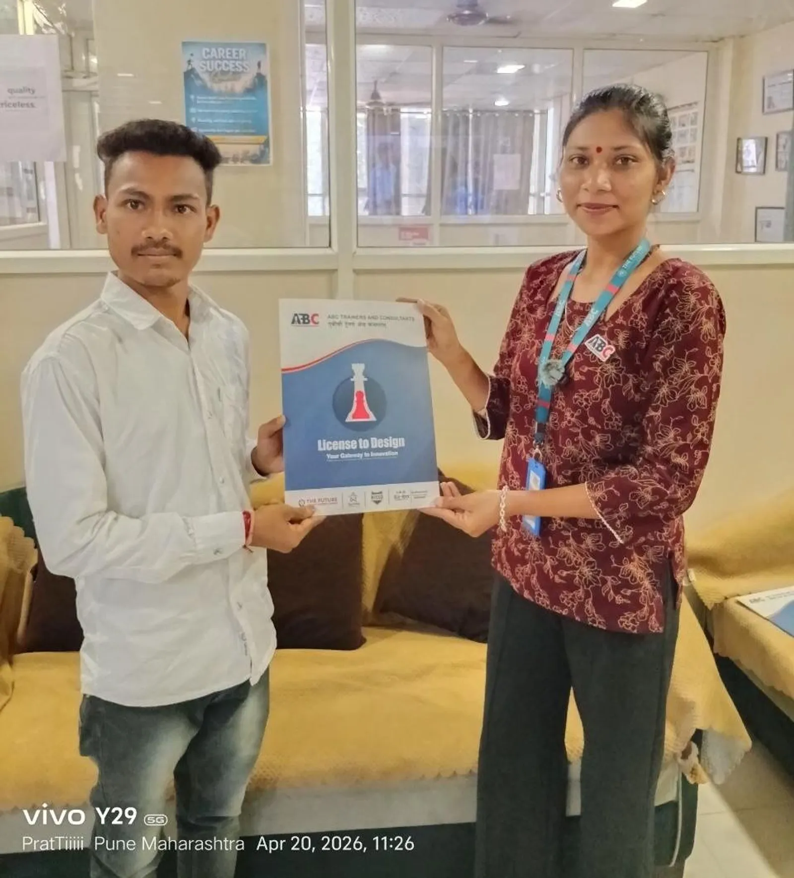
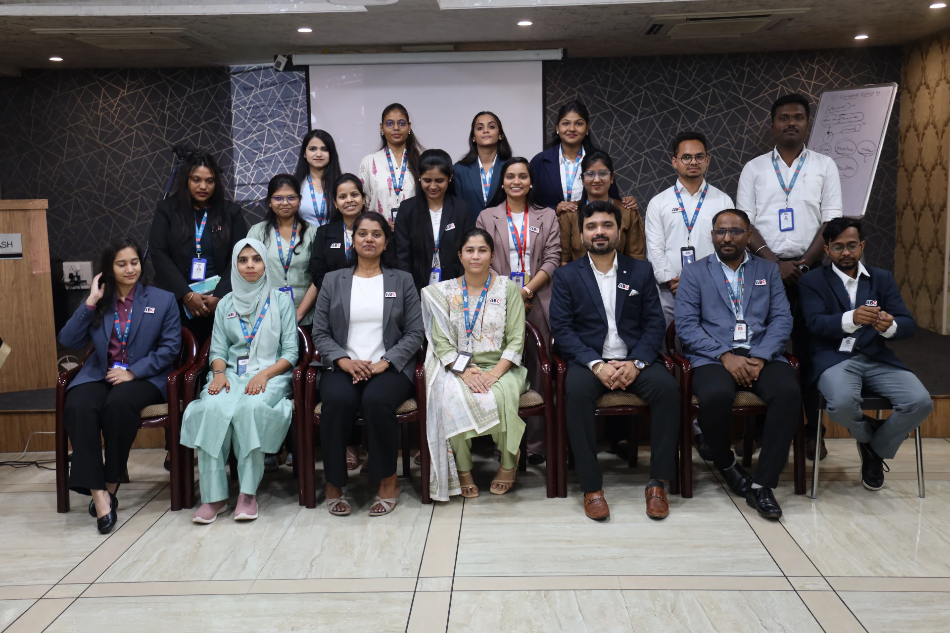
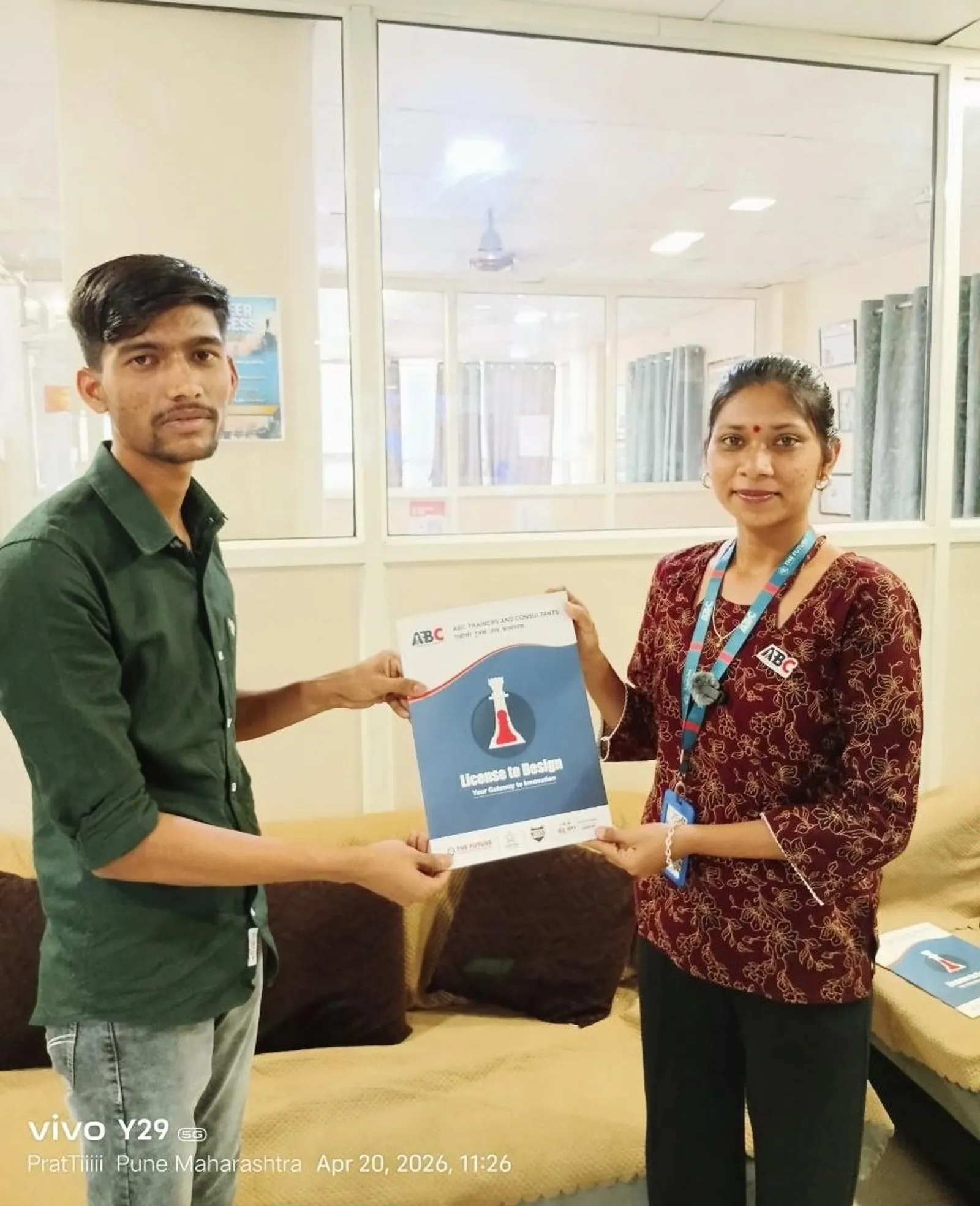
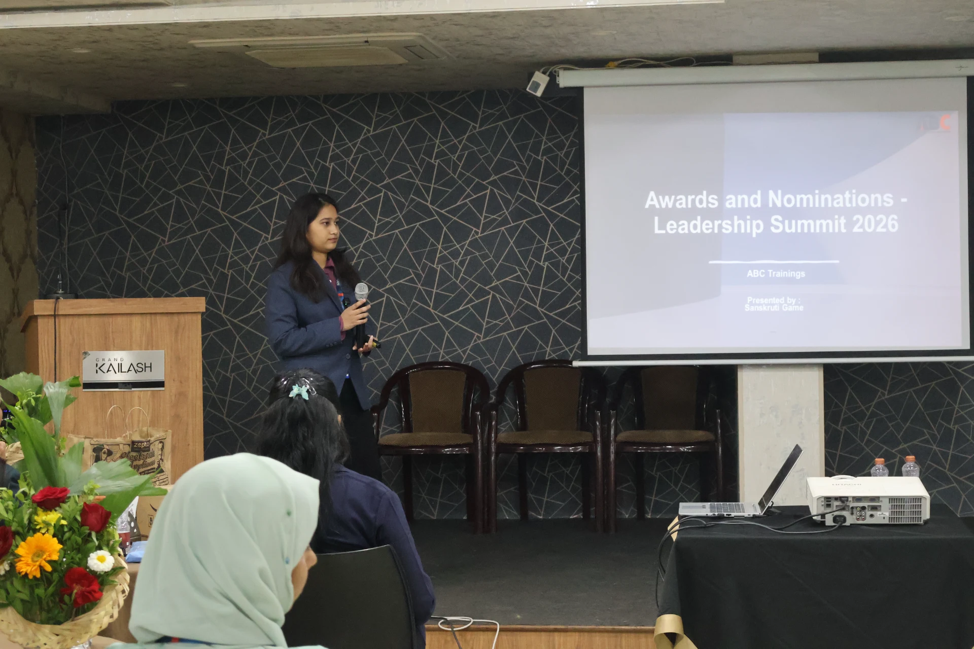
Real ABC students, real sessions

Photos from hands-on Creo Parametric sessions, workshops and labs across our centres.

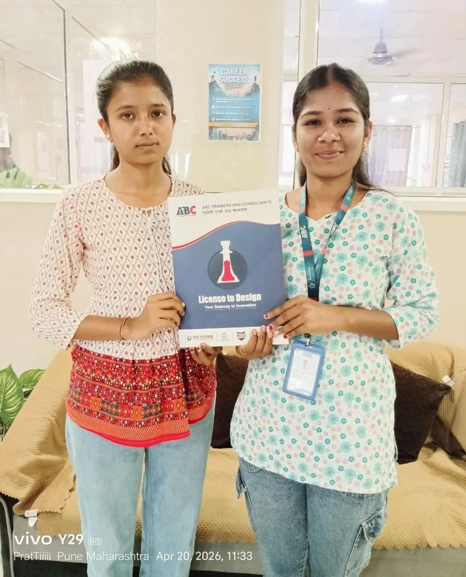
Creo Parametric session at ABC Trainings
Wagholi, Pune
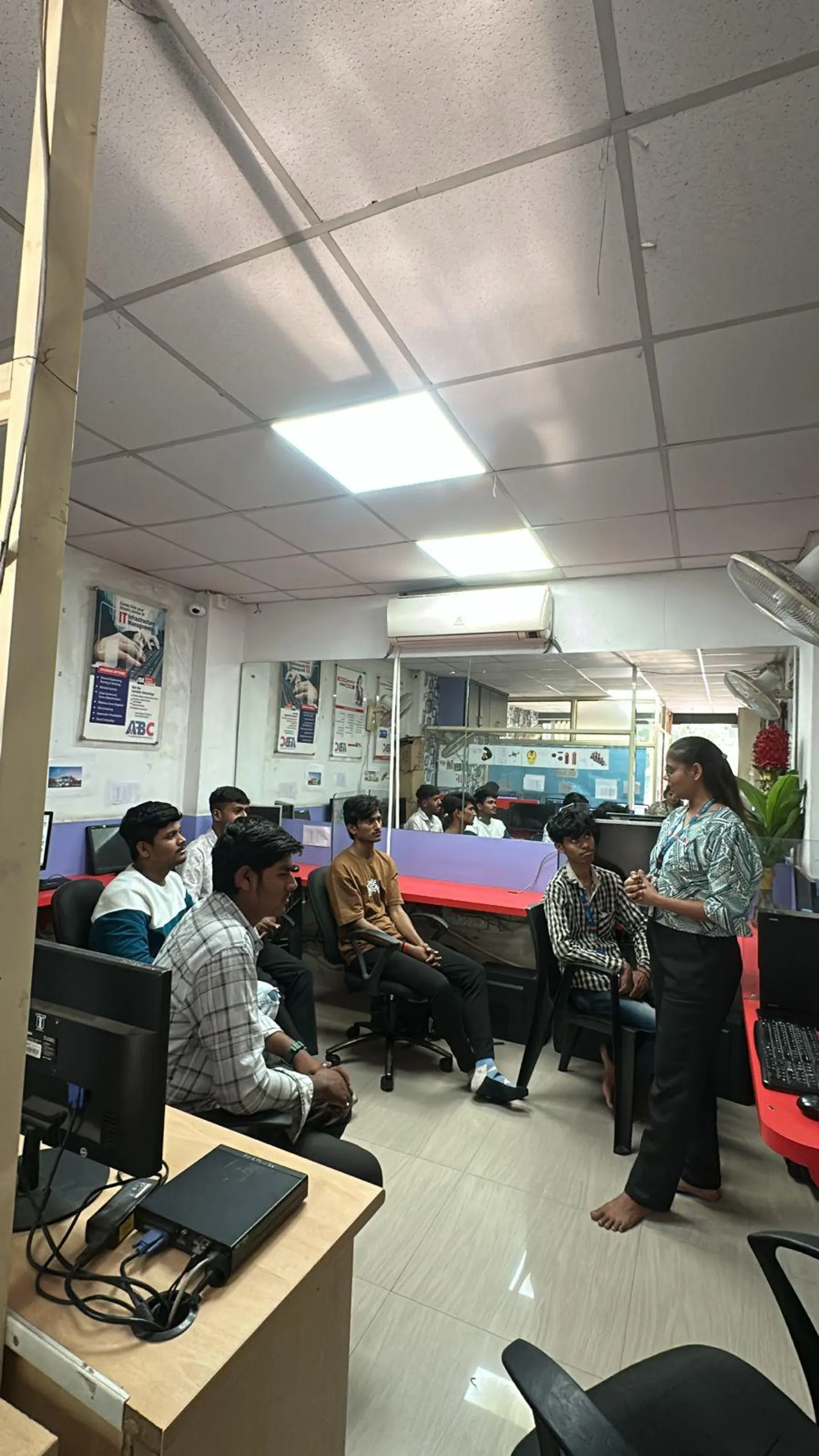
Creo Parametric session at ABC Trainings
Wagholi, Pune
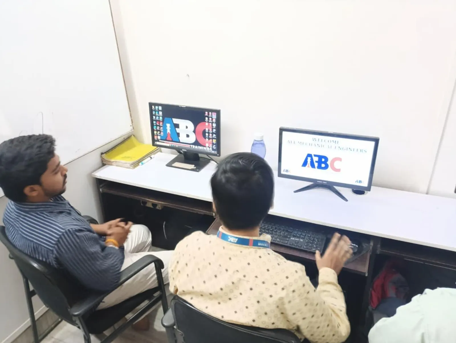
Creo Parametric session at ABC Trainings
Wagholi, Pune
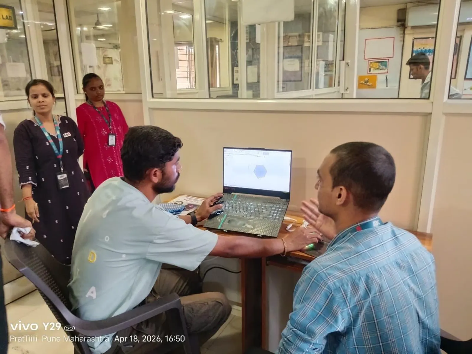
Creo Parametric session at ABC Trainings
Wagholi, Pune
Creo Parametric session at ABC Trainings
Wagholi, Pune
Creo Parametric session at ABC Trainings
Osmanpura, Chh. Sambhajinagar
Creo Parametric session at ABC Trainings
Cidco, Chh. Sambhajinagar
Creo Parametric session at ABC Trainings
Wagholi, Pune

Who teaches it

Industry-grade trainer roster

These are the working professionals who deliver the Creo Parametric program across Maharashtra.

Shubham L. Choundiye Sir

Osmanpura CAD

AutoCAD Mechanical, Creo Parametric, CATIA, SolidWorks, NX CAD, NX CAM, ANSYS Workbench, GD&T

Khan Faeqa Firdous Ma'am

CIDCO

AutoCAD, CATIA V5, Creo, SolidWorks, NX CAD, NX CAM, ANSYS Workbench

Manoj Mangate Sir

Osmanpura CAD

AutoCAD, SolidWorks, CATIA, Creo, NX CAD, NX CAM

Madhuri Waghamode Ma'am

Sangli

CAD, CAM, CAE software

Rohit Ramesh Shinde Sir

Latur

AutoCAD, SolidWorks, CATIA, Creo

Vijay Parshuram Patil Sir

Dhanori

CATIA, SolidWorks, Creo, AutoCAD

Alisha Nasir Mujawar Ma'am

Hadapsar

Creo, CATIA, SolidWorks, AutoCAD, GD&T, NX CAD

Rahul Pralhad Pargave Sir

Sangli

Mechanical AutoCAD, SolidWorks, CATIA, Creo, ANSYS

Who's hiring

19+ active openings hiring Creo Parametric graduates

Snapshot of recent and currently active roles in our hiring-partner network where Creo Parametric is a primary requirement. Salary is shown as posted by the employer.

CompanyRoleSalaryCity
Universal SolutionsDesign EngineerNot disclosedChh. Sambhajinagar
Sudarshan Saur Shakti Pvt. LtdDesign EngineerNot disclosedChh. Sambhajinagar
PRYM Aerospace Pvt LtdCAD EngineerNot disclosedJalna
Atomberg Technologies Pvt LtdDesign Development Engineer₹22K/moPune
Technoguard Solution LLPDesign EngineerNot disclosedPune
Unicraft Appliances Pvt LtdDesign Engineer₹15K-20K/moChh. Sambhajinagar
NPSE Automation Pvt LtdDesign EngineerNot disclosedChh. Sambhajinagar
GM Manufacturing Service Pvt. LtdCreo Design EngineerNot disclosedPune
Nageshwar IndustriesDesign Engineer₹15K-35K/moChh. Sambhajinagar
Rotadyne Precision Engineering Pvt LtdDesign EngineerNot disclosedMiraj
Expert Global Solutions (an Alten company)Design Engineer₹2.3-2.5 LPAChh. Sambhajinagar
Vaibhav IndustryDesign Engineer₹2.5-5 LPALatur

What graduates earn

Salary range for Creo Parametric roles

Range derived from 19+ recent hiring-partner postings tagged with Creo Parametric skill requirements.

Entry level

₹15K/mo

Fresher / trainee

Typical mid

₹18K-25K

₹2.5-3.5 LPA

Senior / experienced

₹40K+/mo

2+ years of experience

Range from Creo Parametric-tagged hiring partner postings; senior product design engineers earn ₹4-6 LPA

In our students' words

What ABC Trainings students say

Verified reviews from students across our centres · 21 reviews · average rating 5 / 5.

I completed the Creo Parametric course at ABC Trainings, Cidco, under the expert guidance of Shubham L. Choundiye Sir. The training was very helpful and easy to understand — I learned 3D modeling, assembly and drafting with practical examples. The guidance was very supportive, and this course has improved my skills and confidence.

Pathan Yunus Khan

Pathan Yunus Khan

Cidco, Chh. Sambhajinagar

I completed the Creo Parametric course at ABC Trainings, Cidco, under the expert guidance of Shubham L. Choundiye Sir. The way Shubham Sir teaches is very good — he covers the Creo software deeply and explains it in a simple, clear way. I really liked his teaching, and ABC Trainings is a great place to learn the software.

Omkar Bhavar

Omkar Bhavar

Cidco, Chh. Sambhajinagar

I successfully completed the Creo course at ABC Trainings, Cidco, under the expert guidance of Shubham L. Choundiye Sir. He is an excellent trainer with deep technical knowledge and a very practical approach. His clear explanations, patience and willingness to solve every doubt made learning easy and effective. The training environment was professional and supportive throughout.

Aditya Salve

Aditya Salve

Cidco, Chh. Sambhajinagar

I completed the Creo Parametric course at ABC Trainings, Cidco, under the guidance of Shubham L. Choundiye Sir. He is a very supportive and knowledgeable trainer — he explains every command and feature step by step, which makes learning easy. His practical examples and doubt-solving sessions helped me understand 3D modeling, assembly and drawing concepts clearly. The environment is friendly and motivating.

Chaitanya Sulakhe

Chaitanya Sulakhe

Cidco, Chh. Sambhajinagar

I completed the Creo Parametric mechanical course at ABC CAD Centre, Osmanpura, under the guidance of Shubham L. Choundiye Sir. It more than met my expectations — a wonderfully practical course, both personally and professionally. I learned so much, and he made even the more complex topics interesting and easy to follow through real-world stories and case studies.

Sachin Navthar

Sachin Navthar

Osmanpura, Chh. Sambhajinagar

I completed the Creo Parametric course at ABC Trainings, Cidco, under the expert guidance of Shubham L. Choundiye Sir. The teaching methodology was clear, practical and industry-oriented — each concept was explained in a simple, understandable way that made it easy to learn and apply. The classroom environment was positive, supportive and well-maintained, which made the whole experience even more effective.

Shubhangi Zalte

Osmanpura, Chh. Sambhajinagar

The Creo Parametric training at ABC CAD Centre under the guidance of Pinky Dhagekar Ma’am was very informative and well organised. She explained each concept with clarity and patience, which made the sessions easy to follow and practically useful. Her professional teaching style and supportive approach created a positive learning environment. Overall it was a great experience that enhanced my CAD skills.

Sakshi Nikam

CAD Centre, Chh. Sambhajinagar

My learning experience in SolidWorks, CATIA and Creo Parametric under the guidance of Madhuri Ma’am was invaluable. The pace of the courses was just right, giving enough time to practice and solidify understanding without feeling rushed. Her clear explanations of the core concepts in each software were very helpful, and she answered every question thoroughly and patiently.

Vaibhavi Anuse

Sangli

Successfully finished the Creo Parametric course at ABC Trainings, CIDCO under Shubham L. Choundiye Sir. Sincerely thankful to ABC Trainings India for a wonderful learning experience and the practical knowledge gained. The course enhanced my design skills and deepened my understanding of Creo software. Grateful for this opportunity — looking forward to applying these skills professionally.

Kuldeep Kharat

CIDCO Centre · Chh. Sambhajinagar

Next Creo Parametric batch

Join the 281+ Creo Parametric alumni at ABC Trainings.

Hands-on training in 2D sketching, 3D parametric modeling, assembly management and visualization. 8+ trainers · 6 centres · placement support across 12+ partners.