Chh. Sambhajinagar
Osmanpura CAD
S.S.C Board to Peer Bazar Road, In front of Jama Masjid, near Post Office, New Usmanpura, Aurangabad 431005
Follow the official 80-hour AutoCAD Mechanical curriculum across 2D drafting, orthographic and sectional views, GD&T, layouts and production drawings. Confirm the live centre, mode, timetable and written fee.
AutoCAD for Mechanical Engineers
4 reviewed course-capability centres
Placement Support
Confirm current written activities
Choose ABC Trainings when its official 80-hour AutoCAD for Mechanical Engineers curriculum, current teaching-capability centre and written batch terms fit you. The centres below have reviewed active-trainer capability as of 2026-10-01; this does not claim that every centre has a live batch today.
Watch on ABC Trainings
Introduction to AI-powered tools inside AutoCAD Mechanical, the first lesson of the Proficient Course series.

ABC Trainings offers AutoCAD for Mechanical Engineers with the 80 instructional hours duration listed on this page at ABC CAD Centre, Osmanpura, Chh. Sambhajinagar; ABC CAD & IT Trainings, CIDCO, Chh. Sambhajinagar; ABC CAD & IT Trainings, Wagholi, Pune; ABC CAD & IT Trainings, Hadapsar, Pune. This page also shows 699+ verified reviews. Confirm the live centre, trainer, delivery mode, timetable and complete written fee before paying.
Published
Course Outcomes
Linked evidence page
Reviewed
Portfolio Projects
Practical course work
Included
Placement Support
Confirm current referral activity
20,000+
Trained Alumni
Since 2014
What You'll Master
The AutoCAD for Mechanical Engineers program is engineered to put you in the seat of a working professional from day one. Every concept is paired with a live exercise, every module ends with a project, and every batch is mentored by an industry expert.
You will walk out with a portfolio of real deliverables — not just a certificate.
Module-by-Module
28 structured modules — from foundations to a placement-ready capstone.
Industry Software Lab
Licensed software, walked through command-by-command on industry workflows.
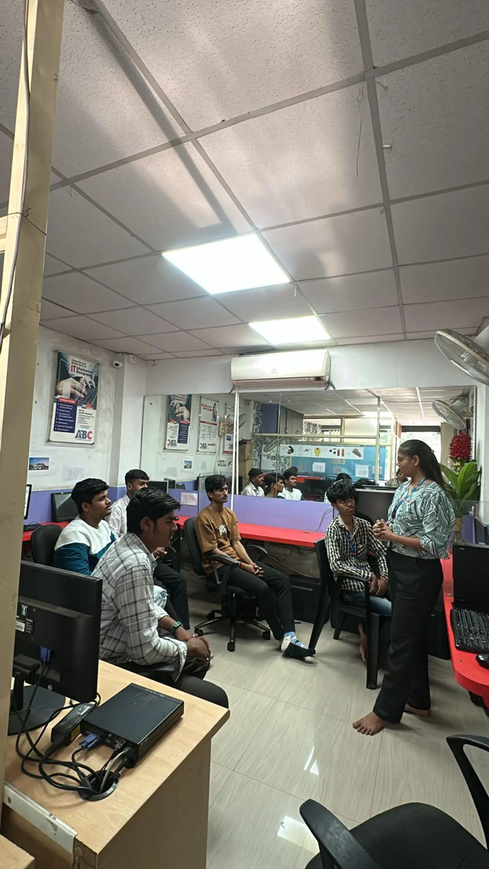
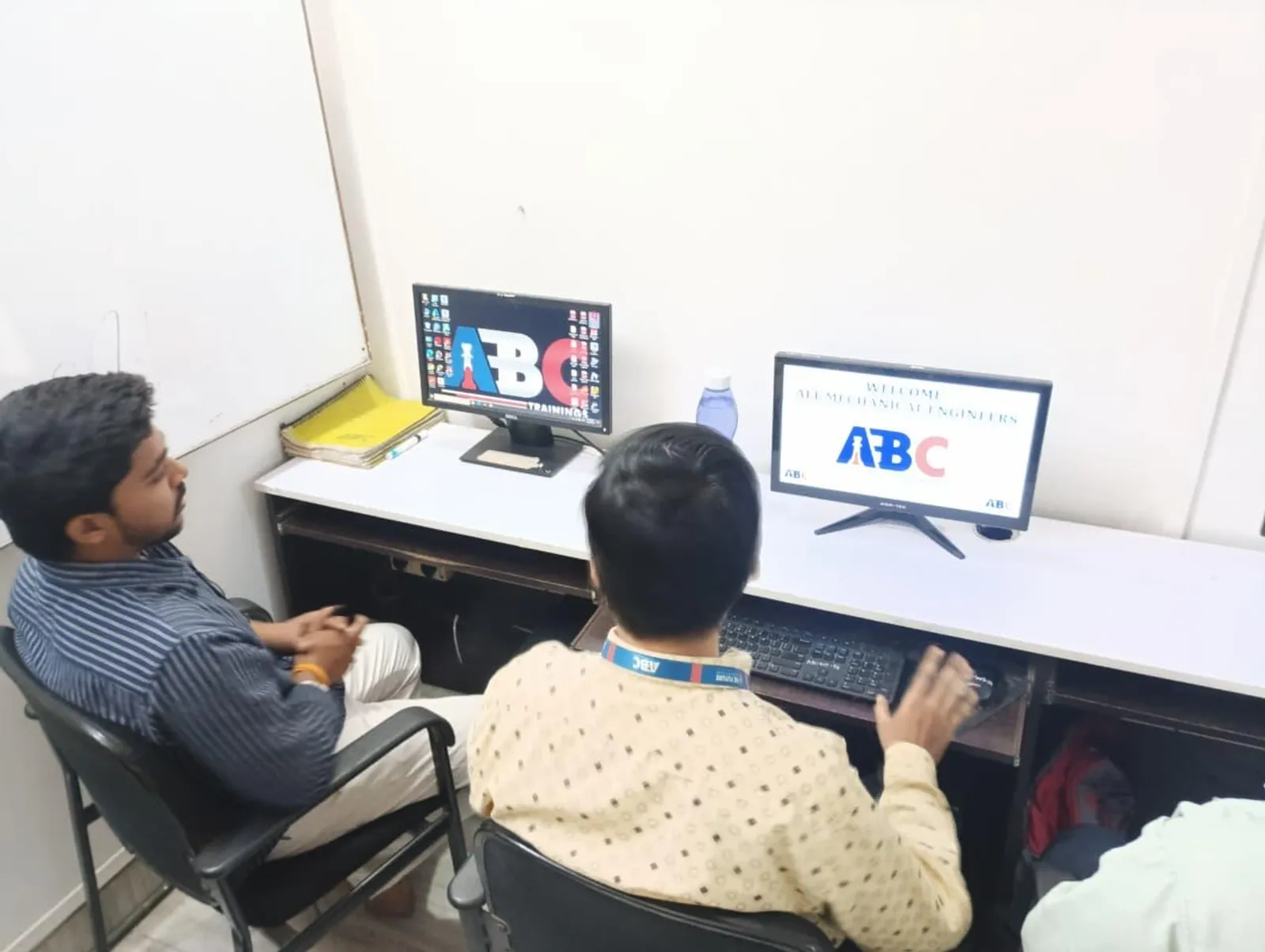
Inside the Classroom
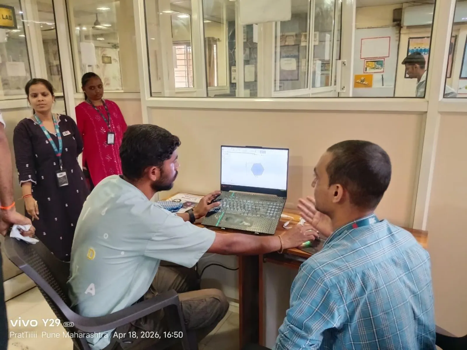
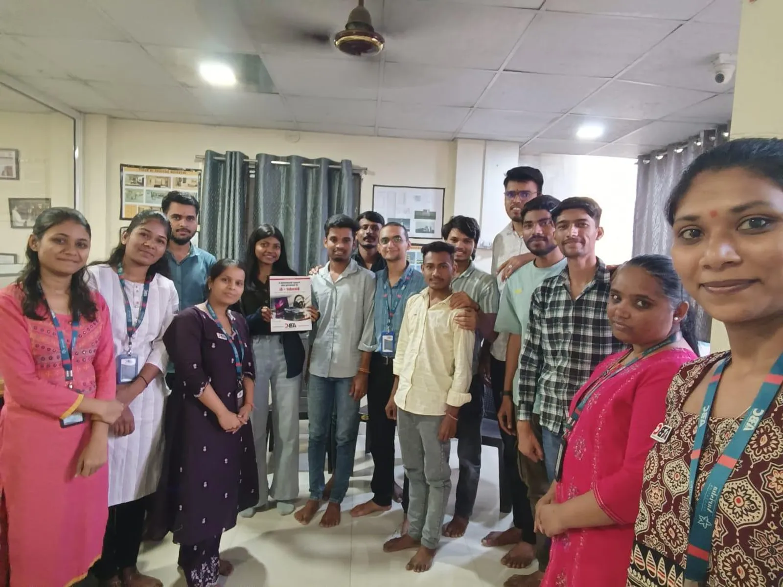
First-party classroom sessions, workshops and learner documentation across our centers in Maharashtra.



Career Outcomes
Placement support includes portfolio review, resume guidance and interview preparation. Course-specific enrolment, review, trainer and hiring evidence is published separately for verification.
Included
Portfolio Review
Included
Interview Practice
Published
Outcome Evidence
Confirm
Current Referrals
“Successfully completed my PLC & SCADA online course. Content was informative and easy to understand. Gained practical knowledge about PLC programming and SCADA systems. Feel more confident working on industrial automation systems.”

Anisha K.
PLC & SCADA (Online) · Online
from Karad, Maharashtra
“Recently completed the AI Powered Tools for AutoCAD course — a very helpful learning experience. Instructor explained concepts clearly and made the tools easy to understand. Now feel more confident using AI tools with AutoCAD in architectural work.”

Santoshi B.
AI-Powered Tools for AutoCAD · Chh. Sambhajinagar
B.E. (Civil) · from Chh. Sambhajinagar, Maharashtra
“Santosh Sir is an amazing instructor. Very supportive and improved my designing skills. It was such a nice experience for learning AutoCAD software.”

Rutuja J.
AutoCAD · Pune
from Pune, Maharashtra
“I completed AutoCAD Mechanical under Shubham Choundiye Sir. The faculty was patient with our queries and the class environment was the best — clean, professional, and focused on results.”

Premkumar K.
AutoCAD Mechanical · Chh. Sambhajinagar
B.Tech · from Buldhana, Maharashtra
“A good course for learning AutoCAD from scratch. Step-by-step guidance from the trainer made learning simple and enjoyable, and the sessions significantly improved my drafting understanding.”

Ishwari Patil
AutoCAD For Civil Engineer & Architect · Sangli
M.Sc · from Sangli, Maharashtra
“This course gave me solid basic knowledge of automation.”

Yogita Kakas
PLC & SCADA · Chh. Sambhajinagar
12th · from Jalna, Maharashtra
Locations
These centres have active-trainer capability for this official course. Confirm the live batch, mode and timetable before enrolment.
Chh. Sambhajinagar
S.S.C Board to Peer Bazar Road, In front of Jama Masjid, near Post Office, New Usmanpura, Aurangabad 431005
Chh. Sambhajinagar
Plot No 258, Ground Floor, Opposite Eiffel Tower, N-1, CIDCO, Aurangabad 431003
Pune
1st Floor, Laxmi Datta Arcade, Pune - Ahmednagar Hwy, Wagholi, Pune 412207
Pune
1st Floor, S.no 156/3, Shree Tower, Pune - Solapur Rd, opp. Vaibhav Theater, Laxmi Vihar, Besides Bloom Hotel, Magarpatta, Hadapsar, Pune 411028
Admissions
Ask admissions for the current centre, trainer, mode, timetable, written fee, cancellation terms and placement-support activity before enrolment.
Written fee quotation
Request the complete current fee and payment schedule in writing before paying.
ABC Trainings course certificate
ABC Trainings issues the course completion certificate; it is not a government, university or software-vendor credential unless separately documented.
Placement-support terms
Confirm the current resume, portfolio, interview and referral activity; no employer or job outcome is guaranteed, and no salary or timeline is promised.
Current batch confirmed by admissions
Ask for the current centre, mode and schedule before enrolment.
Admissions open
Free career counselling
Get the exact fee, payment options & next batch date for your profile — talk to a counsellor, no obligation.
Duration
80 instructional hours
Mode
Current mode: confirm before enrolment
Next batch
Confirm with admissions
Mon–Sat, 9:00 AM – 8:00 PM
Frequently Asked
Everything you need to know before joining.
From Our Guides
Deep-dive reads from the ABC Trainings blog — fees, career paths, tools and real student outcomes.
Review the official curriculum and published course outcomes, then confirm the current batch with admissions.
Plan your course
Compare the official course record with the syllabus on this page. The fee, when published, belongs to the named course below.
Official course · 1
Individual catalogue courses run at these ABC centres. Pick your course and visit the nearest centre for a free demo.
Course hours are instructional hours, not calendar months. Individual course fees are catalogue starting prices excluding GST; programme fees include GST. Fees reviewed ; course records reviewed .
Get the exact fee for your course, centre and mode
Your 2026 guide to a design career: what CAD, CAM & CAE are, the roles & salaries, the companies hiring across Maharashtra, and the exact roadmap to job-ready. Drop your number and read all 24 pages instantly — right here on the site.
By submitting you agree to be contacted by ABC Trainings about CAD & design courses. No spam.
Explore the drawing workflow
Follow a plate from coordinates and circles to top, front and right-side views. Switch views, separate dimensions from centre lines, then work through a size change. This connects the drawing tools to the decisions you make when checking a mechanical drawing.
Fictional teaching exercise: a 120 × 80 × 10 mm mounting plate with four Ø10 mm through holes. Every view below describes this same practice part.
All drawing dimensions are in millimetres. Draw the model at 1:1: one model unit equals 1 mm. Coordinates use the lower-left corner of the top view as (0, 0), with x to the right and y upward; z measures plate thickness.
The official AutoCAD for Mechanical Engineers course is 80 instructional hours. Its published modules connect coordinate entry, geometry, layers, dimensions, projected views and plotting. Use this exercise to explore that component-drawing workflow; compare the Civil and Architecture course when your drawing focus is plans and elevations.
Read the labelled dimensions for size; the drawings resize on screen. On a narrow screen, scroll within a drawing to inspect its full width.
Use decimal millimetres and draw the top-view rectangle from (0, 0) to (120, 80). Keep the model at full size. Record the 10 mm thickness for the front and right-side views.
Inspect: Use distance and coordinate inquiries: the horizontal edge is 120, the vertical edge is 80 and the opposite corner is (120, 80). Changing a viewport scale must leave these model measurements unchanged.
Draw Ø10 circles at (20, 20), (100, 20), (20, 60) and (100, 60). Use the coordinates or copy the first circle by 80 mm along x and 40 mm along y, retaining four distinct circles.
Inspect: Radius = 10 ÷ 2 = 5 mm. Centre spacing is 100 − 20 = 80 mm along x and 60 − 20 = 40 mm along y. The closest hole edge is 20 − 5 = 15 mm from the plate edge.
Project x and z into the 120 × 10 front view; project y and z into the 80 × 10 right-side view. Show the through-hole boundaries as hidden lines at centre coordinate ±5 mm. Keep the shared length, width and thickness aligned when arranging the views on a sheet.
Inspect: Front hidden edges: x = 15, 25, 95, 105. Right-side hidden edges: y = 15, 25, 55, 65. Each pair extends through the full 10 mm thickness. Two holes overlap at each projected centre; the top view establishes all four locations.
Use separate visible-outline, hidden-edge, centre-line and dimension layers in the CAD drawing. Apply continuous visible edges, dashed hidden edges and a centre linetype for axes. Add the 120, 80 and 10 overall dimensions, hole-centre offsets and a four-hole Ø10 callout with associative dimensions.
Inspect: Check the line patterns in the plotted view. The browser groups visible and hidden edges as geometry, with dimensions and centre lines separately switchable. Turning off dimensions must leave the part outline and its holes intact.
Save a new revision, change the plate length and move the right-hand hole column to preserve its edge offset. Update the top and front views, then recheck the side view and every associative dimension.
Inspect: A longer plate changes the x coordinates and front-view length. Width, thickness, hole diameter and the y positions stay fixed. Use measured geometry to confirm the update instead of typing new dimension text over an unchanged drawing.
Create an A4 landscape layout, arrange the three labelled views and set a locked viewport to 1:2. Plot the layout at 1:1. Set annotation sizes for the sheet, preview lineweights and hidden lines, then inspect the PDF.
Inspect: At 1:2, the original 120 mm length occupies 60 mm on paper, the 80 mm width occupies 40 mm and the 10 mm thickness occupies 5 mm. Dimension text still reports model sizes. Check that no label or view is clipped and that the selected paper size is retained.
Increase the plate length from 120 to 140 mm. Keep the 80 mm width, 10 mm thickness, four Ø10 holes and 20 mm hole-centre offsets from the nearest edges. Find the new four centre coordinates, horizontal pitch, three view sizes and the increase in net top-face area.
The new right-hand centre coordinate is 140 − 20 = 120 mm. The centres become (20, 20), (120, 20), (20, 60) and (120, 60). Horizontal pitch is 120 − 20 = 100 mm; vertical pitch stays 40 mm. The top view is 140 × 80, front view 140 × 10 and right-side view 80 × 10 mm. Front hidden edges for the moved holes become x = 115 and 125 mm; the other hidden edges stay fixed. Net top-face area changes from 120 × 80 − 4 × π × 5² = 9,600 − 100π to 140 × 80 − 4 × π × 5² = 11,200 − 100π mm²: an increase of 1,600 mm². Hole-edge clearance remains 20 − 5 = 15 mm.
Talk to a counsellor
Fastest — reply in 2 min
Call us
+91 70391 69629
Mon–Sat, 9:00 AM – 8:00 PM